Method for compensating for deactivated printing nozzles in an inkjet system

A technology of inkjet printers and nozzles, applied in printing, printing devices, etc., can solve problems such as hardware redundancy and low efficiency, and achieve the effects of avoiding overcompensation, improving image quality, and eliminating redundant structures

Active Publication Date: 2018-07-10
HEIDELBERGER DRUCKMASCHINEN AG
View PDF11 Cites 1 Cited by
  • Summary
  • Abstract
  • Description
  • Claims
  • Application Information

AI Technical Summary

Problems solved by technology

[0008] It is therefore the object of the present invention to disclose a method for compensating for deactivated printing nozzles in an inkjet printer which overcomes the disadvantages of the known methods with regard to hardware redundancy and inefficiency

Method used


Image

  • Method for compensating for deactivated printing nozzles in an inkjet system
  • Method for compensating for deactivated printing nozzles in an inkjet system
  • Method for compensating for deactivated printing nozzles in an inkjet system

Examples


Embodiment Construction

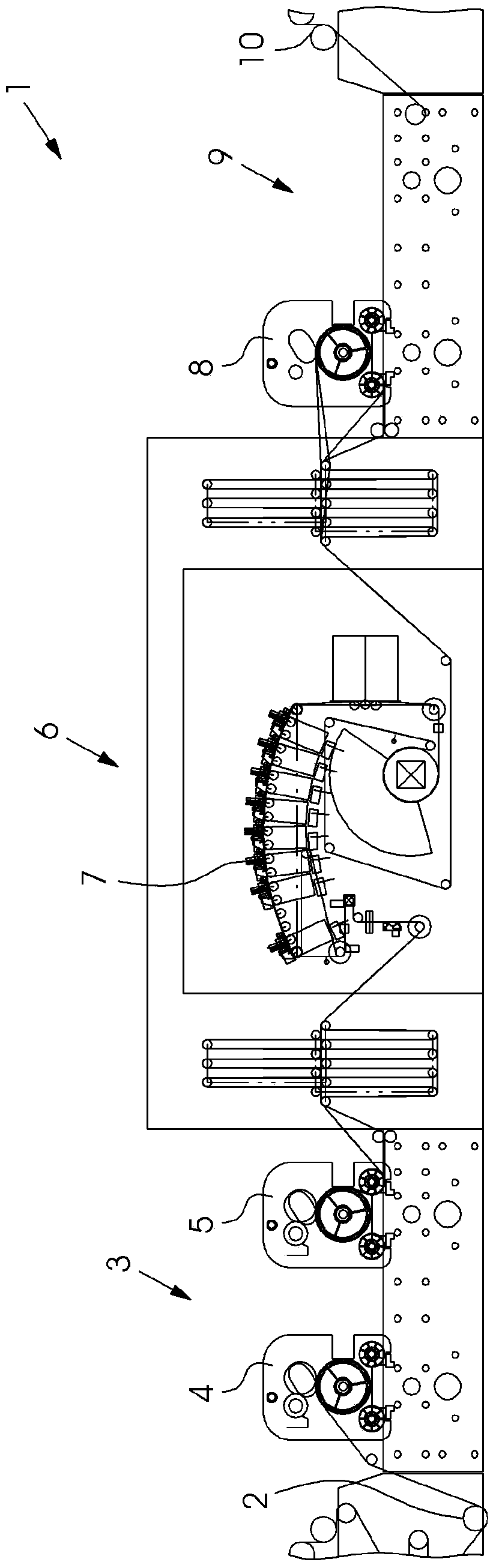
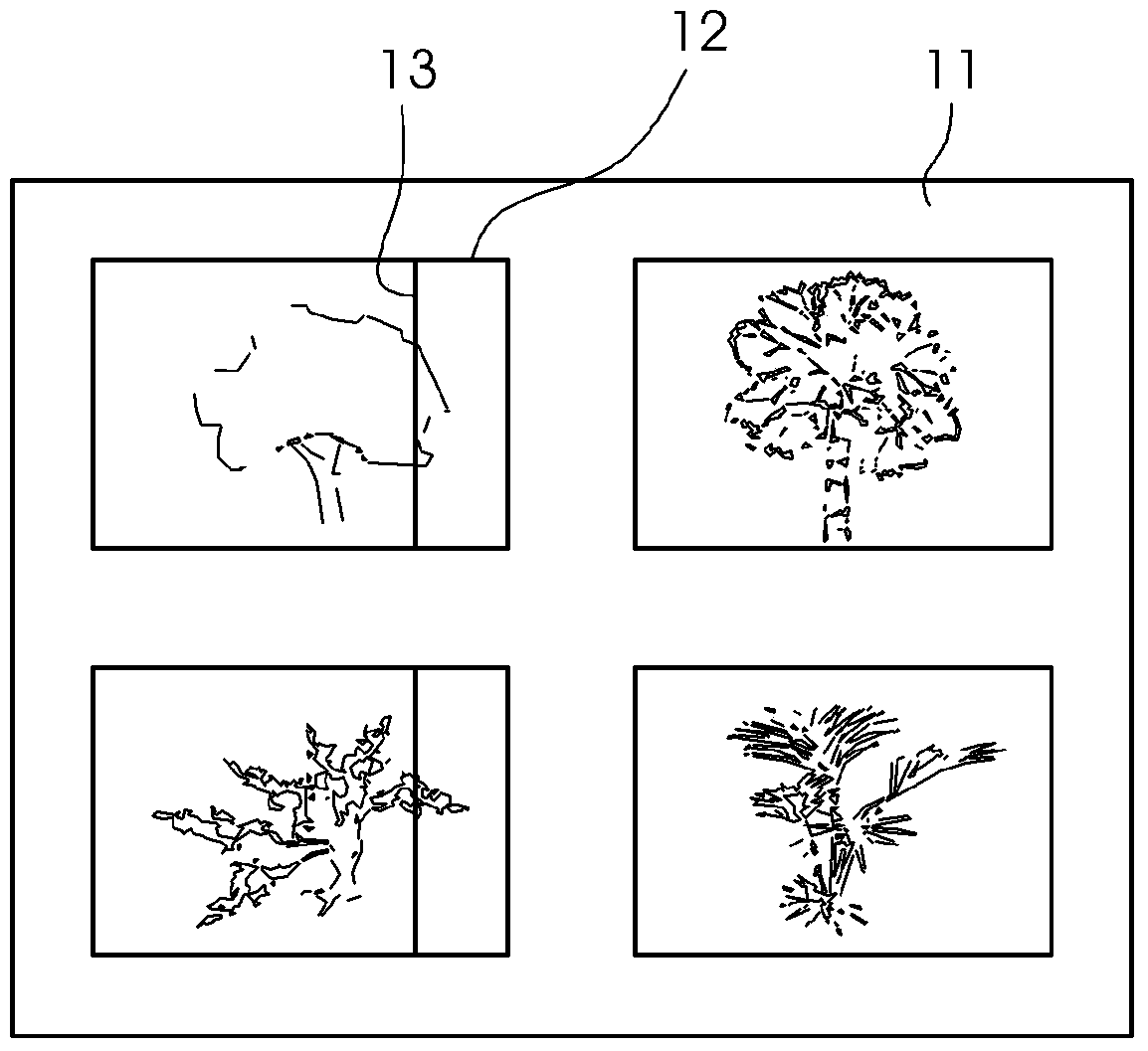
[0047] In a preferred embodiment variant, this field of application is the inkjet printing machine 1 . exist figure 1 An example of a structure for such a machine 1 is shown in . During operation of the printing press 1 , as already explained at the outset, individual printing nozzles in the printing head 7 in the printing unit 6 can become deactivated. The result is then a white line 13, or, in the case of multicolor printing, distorted color values. An example of such a white line 13 is in figure 2 shown in .

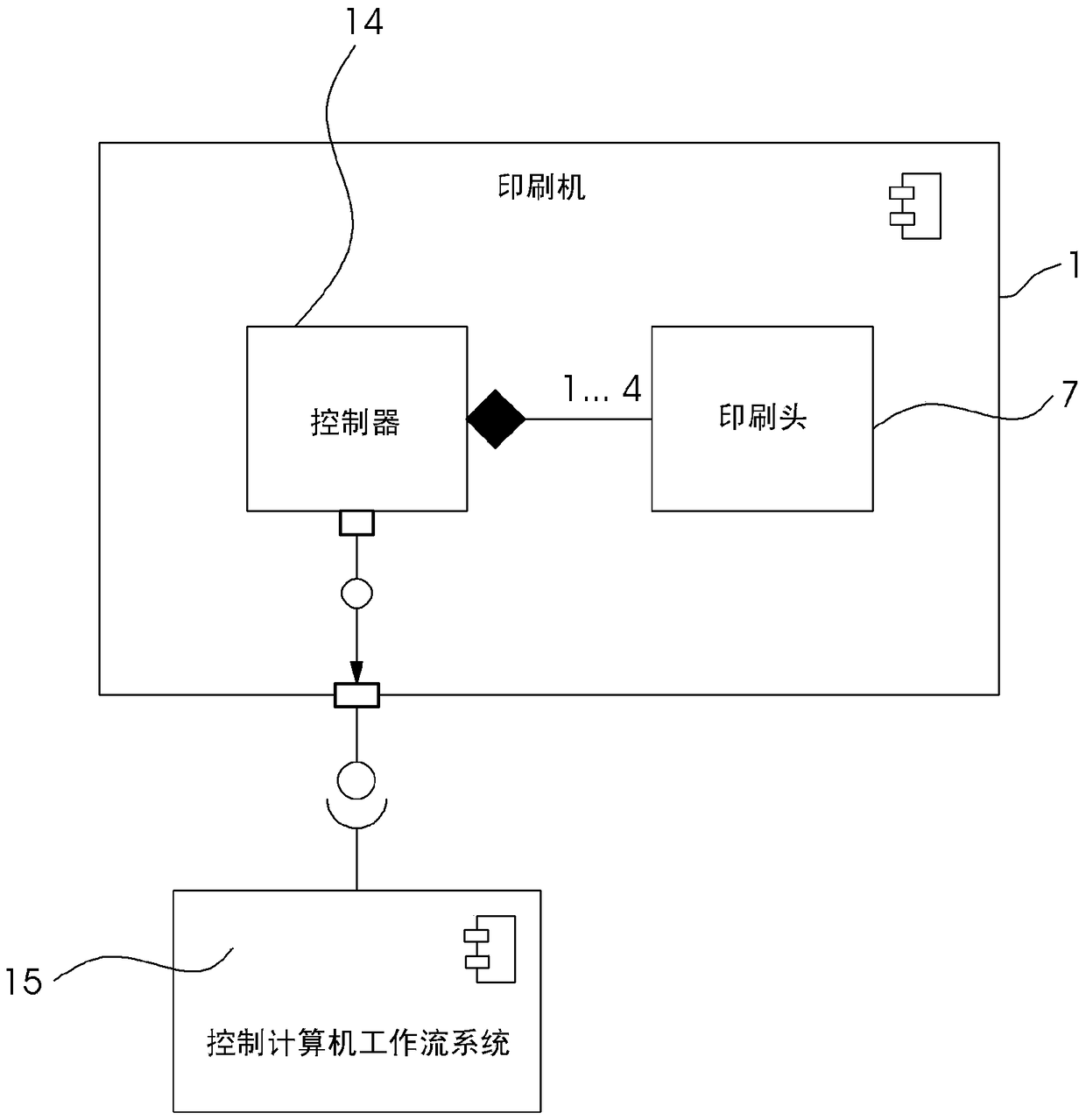
[0048] Since the described method is inefficient to be carried out manually by a user, this execution is carried out automatically by the control computer 14 of the inkjet printer 1 . image 3 An exemplary structure of such a system is shown. This automated method is integrated into the workflow of the printing press 1 here. The configuration of the control computer 15 with respect to the individual method steps can be corrected manually by the user if necessar...


PUM


Abstract

A method for automatically compensating deactivated printing nozzles by means of a control computer in an inkjet printing machine has the steps of: printing a test form for a certain combination of materials; analyzing the printing of the test form, and constructing a look-up table including the values ​​from 0 to 1 Compensation probability; detecting inactivated printing nozzles; reading the rated droplet size to be compensated at the position of inactivated printing nozzles from the printing data; calculating the local area density at the position of inactivated printing nozzles; reading from the lookup table by calculating the local area density Compensation probability; calculate the pseudo-random number between 0 and 1 for the right and left adjacent pixels of the pixel to be compensated; if the corresponding pseudo-random number of the right and left adjacent pixels of the pixel to be compensated is less than the pseudo-random number read from the lookup table When the compensation probability is reached, increase the drop size of adjacent pixels; calculate the size of all the rated drop points and adjacent drop points to be compensated on the position of the deactivated printing nozzle, and apply the changed drop point size to the printing data; use the changed printing data Execute printing tasks.

Description

technical field [0001] The invention relates to a method for compensating for deactivated printing nozzles in an inkjet system. [0002] The invention is in the technical field of digital printing. Background technique [0003] Inkjet printers typically include one or more print heads, and each print head includes one or more print nozzles. Inkjet printers use nozzles to print by firing ink. Such inkjet printers have a nozzle plate with a special arrangement of the individual nozzles which allows a resolution of up to 1200 dpi. This requires a nozzle pitch of approximately 20 μm. When individual printing nozzles are deactivated, regions are produced which cannot be drawn by the nozzles provided for this purpose in terms of single color separations (according to BCMY). This results in a colorless location, which may appear as a white line. If multicolor printing is involved, the corresponding color is missing at this point and the color values ​​are distorted. It should...

Claims


Application Information

Patent Timeline
Patent Type & Authority Patents(China)
IPC IPC(8): B41J2/165
CPCB41J2/2146B41J2/2142B41J2/2139B41J29/393B41J2/01B41J2/0451B41J2/16579
Inventor H·克勒R·蒂塔
Owner HEIDELBERGER DRUCKMASCHINEN AG
Why Eureka
Try Eureka