
Thin-wall square box hollow floor mandrel and anti-floating method thereof

A hollow floor and mandrel technology, applied in the direction of floors, formwork/formwork/work frames, building components, etc., can solve the problems of increasing labor intensity of workers, reducing construction efficiency, slow construction progress, etc., to improve the reuse rate , Reduce construction cost and improve construction quality

Active Publication Date: 2016-05-25
ARCHITECTURAL DESIGN RES INST OF GUANGDONG PROVINCE
View PDF6 Cites 1 Cited by
  • Summary
  • Abstract
  • Description
  • Claims
  • Application Information

AI Technical Summary

Problems solved by technology

[0005] (1) The steel wire passes through the template to fix the anti-floating steel mesh on the frame support system. The length of the steel wire is long, and the bending stiffness of the anti-floating steel bar is small, resulting in poor anti-floating effect and affecting the construction quality
[0006] (2) The mandrel is light in weight, and it is easy to shift horizontally when pouring concrete, and the steel wires around the mandrel are difficult to control the horizontal shift of the mandrel, which further affects the construction quality
[0007] (3) The number of steel wires is large, and correspondingly, the number of holes on the formwork is also large, so that the formwork cannot be reused, which increases the construction cost
[0008] (4) There are many fixed points of steel wire on the anti-floating steel mesh and frame support system, and the number of holes punched on the formwork increases the labor intensity of workers, which is time-consuming and laborious. The construction progress is slow and the construction efficiency is reduced.

Method used


Image

  • Thin-wall square box hollow floor mandrel and anti-floating method thereof
  • Thin-wall square box hollow floor mandrel and anti-floating method thereof
  • Thin-wall square box hollow floor mandrel and anti-floating method thereof

Examples


Embodiment Construction

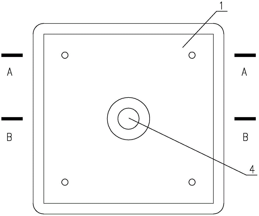
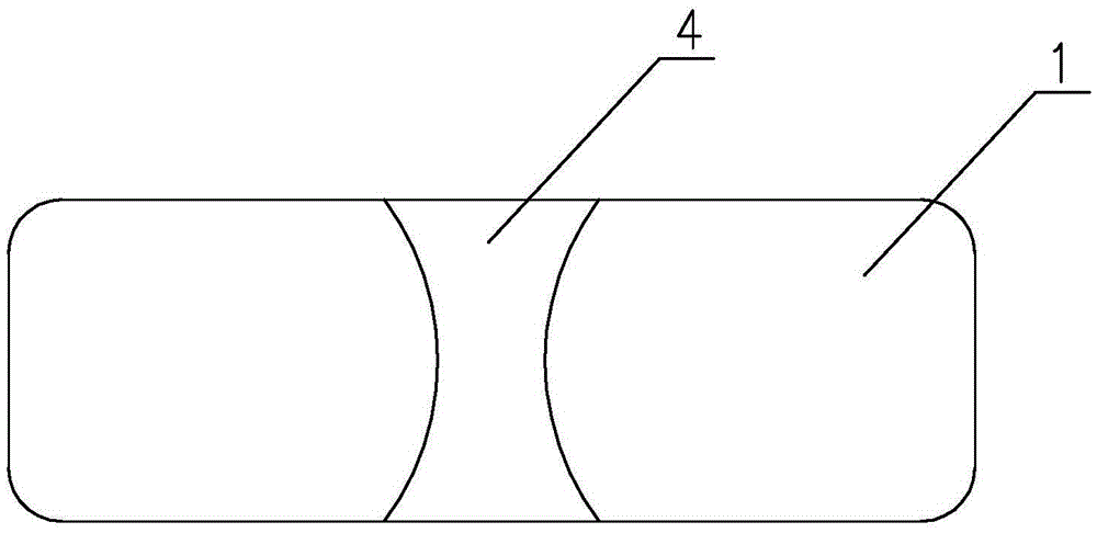
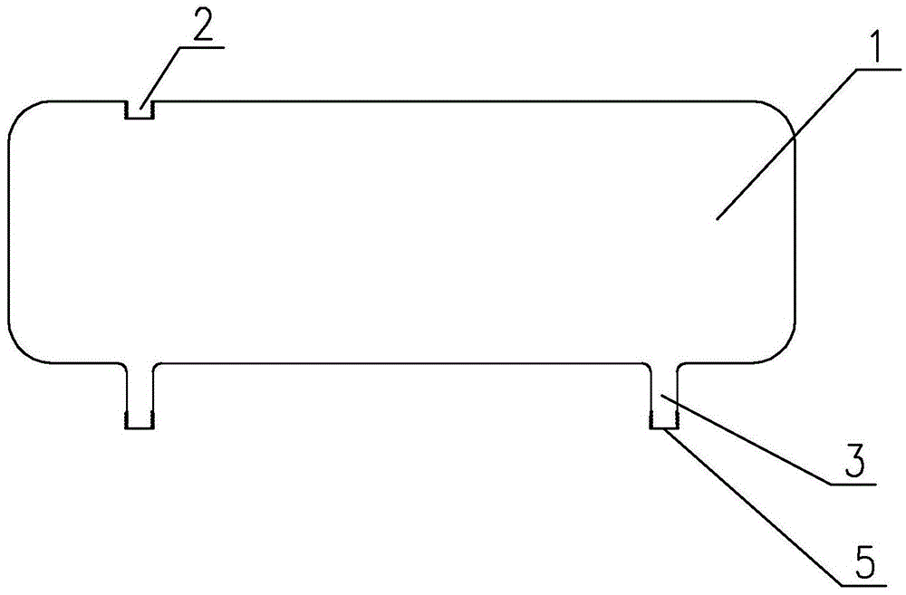
[0037] Such as Figure 1~4 As shown, it is a thin-walled square box hollow floor mandrel 1 of the present invention, which is a block body with a hollow cavity, generally square or rectangular, and is provided on the mandrel 1 for injecting liquid into the mandrel. 1, the liquid injection hole 2 that can be opened and closed, the liquid injection hole 2 is located on the top surface of the mandrel 1, specifically, a plug is provided on the orifice of the liquid injection hole to realize the opening and closing of the liquid injection hole. On the bottom surface of the mandrel 1, at least three supports 3 for supporting on the formwork are evenly distributed. In this embodiment, there are four supports 3, which are respectively located at the four corner positions of the mandrel. The bottom surface of the mandrel 1 is also provided with an openable and closable tubular drain hole for draining the liquid in the mandrel 1, and the drain hole extends to the formwork. The core mol...


PUM


Abstract

The invention discloses a thin-wall square box hollow floor mandrel and an anti-floating method thereof. The thin-wall square box hollow floor mandrel is a block with a hollow cavity and is provided with an openable liquid injection hole used for injecting liquid into the mandrel, at least three supports used for being supported by a template are evenly distributed on the bottom surface of the mandrel, an openable tubular liquid discharge outlet used for discharging liquid in the mandrel is also formed in the bottom surface of the mandrel, and the liquid discharge outlet extends to the template. By the adoption of the mandrel, construction is easy, the anti-floating effect is good, horizontal movement of the mandrel can be well controlled, and construction quality is improved; the recycle rate of the template is increased, construction cost is reduced, the labor intensity of workers is relieved greatly, and construction efficiency is improved greatly. The mandrel is provided with the supports, and compared with existing mandrels adopting cushion blocks for supporting, the mandrel has the advantage that due to the omission of cushion blocks, extract building materials for floating resistance are not needed; furthermore, liquid used for being injected into the mandrel can be recycled, so that construction cost is further reduced.

Description

technical field [0001] The invention relates to the thin-wall square box hollow floor technology, in particular to a thin-wall square box hollow floor mandrel, and also relates to the anti-floating method of the mandrel. Background technique [0002] The hollow floor is a cast-in-place reinforced concrete floor structure, also known as the cast-in-place beamless hollow floor. The hollow floor includes steel bars, concrete and a mandrel, the mandrel is embedded in the reinforced concrete, and the mandrel is generally a lightweight material. Hollow-core floors are widely used because of their advantages of reducing building weight, increasing building headroom, saving building materials, and reducing overall cost. [0003] The thin-walled square box hollow floor is a reinforced concrete hollow floor with a certain interval of two-way grid cast-in-place ribs formed inside the reinforced concrete floor by regularly embedding thin-walled square box molds in the cast-in-place con...

Claims


Application Information

Patent Timeline
Patent Type & Authority Applications(China)
IPC IPC(8): E04G15/06E04B5/32
CPCE04B5/32E04G15/063
Inventor 张立平徐卫
Owner ARCHITECTURAL DESIGN RES INST OF GUANGDONG PROVINCE
Learn More