

Self-expanding subsidizing device for oil well casing and subsidizing method thereof
An oil well casing and self-expanding technology, which is applied in the direction of earthwork drilling, wellbore/well components, etc., can solve the problems of short subsidy section, casing deformation, high construction risk, etc., and achieve enhanced resistance to internal pressure and external extrusion Excellent performance, reliable sealing and plugging, and strong corrosion resistance
- Summary
- Abstract
- Description
- Claims
- Application Information
AI Technical Summary
Problems solved by technology
Method used
Image

Examples
Embodiment 1
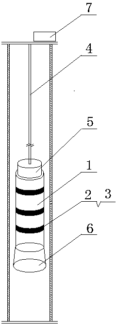
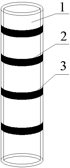
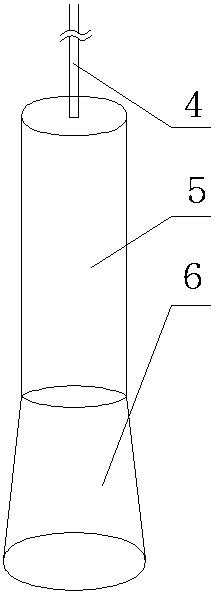
[0024] This embodiment provides an oil well casing self-expanding subsidy device, combined with figure 1 , figure 2 with image 3 As shown, it includes a downhole tool release device and a subsidy pipe, and the subsidy pipe is a memory alloy pipe 1, such as image 3 As shown, the downhole tool release device is composed of a cable 4, a centralizing cylinder 5, a conical limit cylinder 6, and a pressure gauge 7. The pressure gauge 7 is located on the ground, and the pressure gauge 7 is connected to the upper end of the centralizing cylinder 5 through the cable 4. , the lower end of the centralizing cylinder 5 is connected with a tapered spacer cylinder 6 with a small upper end and a large lower end.
[0025] In the structure of this embodiment, the downhole tool release device is used to lower the supplementary pipe to the casing damage position, and the subsidy pipe is heated by the temperature in the well. When the memory alloy pipe reaches the training temperature, it wil...
Embodiment 2
[0027] In the above-mentioned embodiment 1, the memory alloy tube 1 needs to be seated on the tapered limiting cylinder 6 at the beginning to leave the tapered limiting cylinder 6 later. To complete these actions, a special design is required. In this embodiment Described in detail, in this embodiment, the inner diameter of the memory alloy tube 1 is between the inner diameter of the centralizing cylinder 5 and the inner diameter of the lower end of the conical limit cylinder 6. At the beginning, the memory alloy tube 1 is set on the outer seat of the centralizing cylinder 5. On the conical limiting cylinder 6, when entering the well, as the temperature rises, the memory alloy tube 1 expands, and its inner diameter will gradually be greater than the inner diameter of the lowermost end of the conical limiting cylinder 6. At this time, the memory alloy tube 1 will no longer Seat on the conical limiting cylinder 6, it will stick to the casing wall to subsidize the damaged part, an...
Embodiment 3
[0032] This embodiment provides a subsidy method for the aforementioned oil well casing self-expanding subsidy device, combining figure 1 shown, including the following steps:
[0033] Before entering the well, first coat the high temperature resistant adhesive 3 on the outer wall of the rubber sealing ring 2 and the shape memory alloy tube 1, then pass the shape memory alloy tube 1 through the cable 4 and put it on the outside of the centralizing cylinder 5, and its lower end is against the On the middle part of the conical limit cylinder 6;
[0034] Drive the cable 4 through the workover vehicle to lower the subsidy pipe to the casing damage position, let it stand for 30 minutes, and observe the change of the pressure gauge 7;
[0035] When the subsidized pipe is slowly heated by the temperature in the well to reach the training temperature, the subsidized pipe will rapidly self-expand and be firmly attached to the inner wall of the casing, so as to achieve the purpose of r...
PUM
 Abstract
Description
Claims
Application Information