
Fluid Cooler with Self-Wetting Tube Surfaces

A closed cooling tower and cooling tower technology, applied in the field of cooling towers, can solve the problems affecting the heat exchange efficiency of the system, different water film quality, and different heat exchange effects, so as to save spray pump work, uniform water seepage, and surface The effect of full coverage of water film

Active Publication Date: 2017-06-30
UNIV OF SHANGHAI FOR SCI & TECH
View PDF6 Cites 0 Cited by
  • Summary
  • Abstract
  • Description
  • Claims
  • Application Information

AI Technical Summary

Problems solved by technology

[0003] However, there are some weaknesses in the traditional closed cooling tower: the spray water pump will consume a lot of energy in the whole cycle; in addition, due to the multi-layer arrangement of the heat exchange tubes from top to bottom, the spray water is sprayed from top to bottom, The top layers of tubes can directly receive spray water, but most of the lower tubes are wetted by the water dripping from the upper tubes, so that the quality of the water film formed on each layer of heat exchange tubes is different, resulting in different heat transfer effects. The dry surface of the heat exchange tube may have an anhydrous film, which directly affects the heat exchange efficiency of the entire system

Method used


Image

  • Fluid Cooler with Self-Wetting Tube Surfaces
  • Fluid Cooler with Self-Wetting Tube Surfaces

Examples


Embodiment Construction

[0025] The present invention will be further described in conjunction with accompanying drawing and embodiment now. These drawings are all simplified schematic diagrams, which only schematically illustrate the basic structure of the present invention, and therefore only show the configurations related to the present invention.

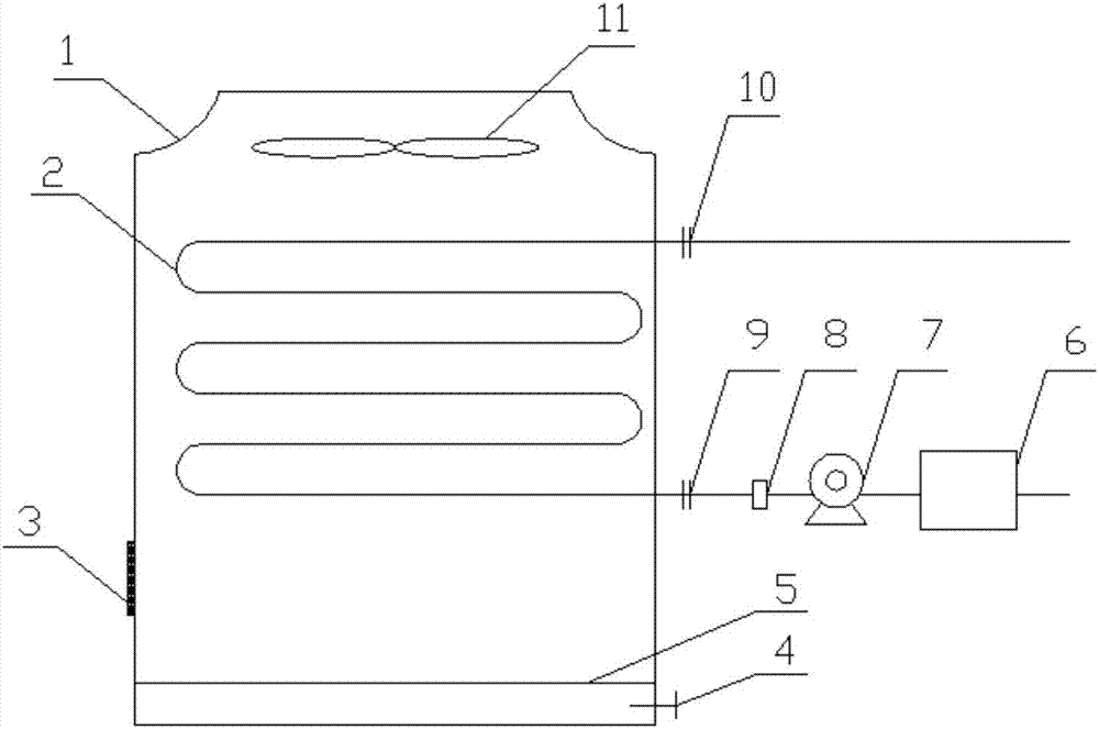
[0026] Such as figure 1 The closed cooling tower of a kind of self-wetting pipe surface shown comprises: tower body 1; The sump 5 that is arranged at the bottom of tower body 1; The fan 11 at the top of the tower body 1; the air inlet grille 3 is provided on the side wall of the tower body 1, and the tower body 1 communicates with the outside air through the air inlet grille 3; There is a drain valve 4; a water inlet 9 and a circulating water pump 7 arranged at the lower part of the self-wetting heat exchange tube 2; and a water outlet 10 arranged at the upper part of the self-wetting heat exchange tube 2.

[0027] Above the self-wetting heat exchang...


PUM


Abstract

The invention provides a closed cooling tower capable of achieving pipe surface self-wetting. The closed cooling tower comprises a tower body, heat exchange pipes, a water collecting tank, a draught fan and an air inlet grille; the heat exchange pipes are located in the tower body, one end of the heat exchange pipes is provided with a water inlet used for introducing water to be cooled into the heat exchange pipes from the outside, and the other end of the heat exchange pipes is provided with a water outlet used for enabling cooled water in the heat exchange pipes to be introduced out; the water collecting tank is arranged in the tower body and located under the heat exchange pipes; the draught fan is arranged at the top of the tower body and located over the heat exchange pipes; the air inlet grille is arranged on the side wall of the tower body, the tower body is communicated with outside air through the air inlet grille, and the upper portions of the surfaces of the heat exchange pipes are provided with a series of small holes, so that the water in the heat exchange pipes can flow out from the small holes to wet the surfaces of the heat exchange pipes. According to the closed cooling tower, a spraying water pump is not needed any more to supply spraying water, and therefore power dissipation of the closed cooling tower is reduced; the uniform seepage quantity and the complete surface water film coverage of all layers of the pipes can be achieved by adjusting the size, the quantity and the space distance of the small seepage holes formed in all layers of the pipes arranged in the adjusting tower.

Description

technical field [0001] The invention belongs to the technical field of cooling towers, in particular to a closed cooling tower with a self-wetting pipe surface. Background technique [0002] In the traditional closed cooling tower, the tube heat exchanger is placed in the tower, the hot water flows in the tube, the spray water pump drives the spray water to spray down from the top of the tower to the surface of the heat exchange tube, and the fan on the top of the tower drives the air from the bottom The upper flow passes through the surface of the heat exchange tube, and the heat in the tube is taken away by the evaporation of water on the surface of the tube and the convection of the air to realize the heat exchange effect. [0003] However, there are some weaknesses in the traditional closed cooling tower: the spray pump will consume a lot of energy in the whole cycle; in addition, due to the multi-layer arrangement of the heat exchange tubes from top to bottom, the spray...

Claims


Application Information

Patent Timeline
Patent Type & Authority Patents(China)
IPC IPC(8): F28C1/00
CPCF28C1/00
Inventor 欧阳新萍刘冰翛李倩高文通舒涛
Owner UNIV OF SHANGHAI FOR SCI & TECH
Learn More