

Compound phase-change material target and preparation method thereof
A composite phase change material and a technology of phase change materials, which are applied to the target of composite phase change materials and their preparation, and the field of composite phase change materials, can solve problems such as uneven distribution, and achieve the effect of solving uneven distribution.
- Summary
- Abstract
- Description
- Claims
- Application Information
AI Technical Summary
Problems solved by technology
Method used
Image


Examples
preparation example Construction
[0035] In addition, this embodiment also discloses a method for preparing the above composite phase change material target, including the following steps:
[0036] 1) Prepare the material with a higher melting point into a cylindrical shape as a matrix, such as figure 1 shown;
[0037] 2) Using an etching process to prepare cylindrical holes with the same size and shape and uniform distribution on the substrate, such as figure 2 As shown, the diameter of the small hole is 0.5-50 μm, and the depth is 0.5-50 μm;
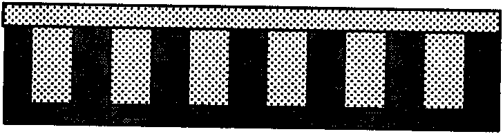
[0038] 3) The material with a lower melting point is filled in the cylindrical small hole, and the two materials are combined through a hot-press sintering process. What is used here is a vacuum hot-press sintering method, such as image 3 shown;
[0039] 4) The surface is treated by mechanical polishing to obtain a smooth, uniform and dense composite phase change material target, such as Figure 4 shown.
Embodiment 1
[0041] Using the phase change material antimony tellurium alloy (Sb-Te) and the non-phase change material Si, the composite phase change material target material-Si of the structure described in the present invention is prepared 2 Sb 2 Te 3 , whose steps are:
[0042] 1) Compared with antimony-tellurium alloy (Sb-Te), the non-phase change material Si has a higher melting point, so Si is prepared into a cylindrical shape as a matrix, such as figure 1 shown;
[0043] 2) Using an etching process to prepare cylindrical holes with the same size and shape and uniform distribution on the Si substrate, such as figure 2 As shown, the diameter of the small hole is 0.5 μm, and the depth is 0.5 μm;
[0044] 3) Sb 2 Te 3 The material is filled in the small holes, and the two materials are combined through the hot pressing sintering process, such as image 3 shown;
[0045] 4) The surface is treated by chemical mechanical polishing to obtain a smooth, uniform and dense composite p...
Embodiment 2
[0047]Using phase change material germanium antimony tellurium alloy (Ge-Sb-Te) and non-phase change material SiO 2 , prepare the composite phase change material target material-(Ge 2 Sb 2 Te 5 ) 0.9 -(SiO 2 ) 0.1 , the steps are:
[0048] 1) Non-phase change material SiO 2 Compared with germanium antimony tellurium alloy (Ge-Sb-Te), SiO 2 The melting point of SiO is higher, so SiO 2 Prepared into a cylindrical shape as a substrate, such as figure 1 shown;
[0049] 2) Etching process is used in this SiO 2 Cylindrical holes with the same size and shape and uniform distribution are prepared on the substrate, such as figure 2 As shown, the diameter of the small hole is 5 μm, and the depth is 5 μm;
[0050] 3) The Ge-Sb-Te material is filled in the small holes, and the two materials are combined through a hot-pressing sintering process, such as image 3 shown;
[0051] 4) The surface is treated by chemical mechanical polishing to obtain a smooth, uniform and dense ...
PUM
| Property | Measurement | Unit |
|---|---|---|
| Diameter | aaaaa | aaaaa |
| Depth | aaaaa | aaaaa |
| Diameter | aaaaa | aaaaa |
Abstract
Description
Claims
Application Information