Device being able to continuously detect thickness of steel belt on line

A technology of steel strip and buffer device, applied in measuring devices, instruments, using ultrasonic/sonic/infrasonic waves, etc., can solve the problems of inconvenient detection, error-prone, influence on the accuracy of steel strip thickness detection, etc., to avoid measurement errors. Accurate, prevent the threat of electric shock, simple and compact structure

Active Publication Date: 2016-05-25
ZHEJIANG UNIV OF TECH
View PDF9 Cites 0 Cited by
  • Summary
  • Abstract
  • Description
  • Claims
  • Application Information

AI Technical Summary

Problems solved by technology

[0003] In the basic construction of steel strip rolling shelves, the shelf factory generally obtains multiple coils of steel strips directly from the steel strip factory, and the thickness of the rolled steel strips is different. Therefore, the total length of two coils of steel strips of the same size is often due to the difference in thickness. They are also different. Often, the thickness of the steel strip will be greatly reduced if the thickness of the steel strip is increased a little. Since the purchase of the steel strip is usually priced by weighing, if the thickness of the steel strip is higher than the actual need, then the same price can be purchased. The length of the steel coil obtained cannot achieve the expected effect, resulting in low cost performance for purchase. Therefore, it is particularly necessary to detect the thickness of the steel strip before production.
Steel strips obtained from the manufacturer are generally packaged in bare packages. Due to transportation, loading and unloading, and storage, the outer surface is not suitable as a sample for inspection. Inspection methods can only be added during the production process to inspect the thickness of the steel strip; at the same time The storage limitations of the steel strip itself make it impossible to move at will. Therefore, it is very inconvenient to measure the thickness of the coiled steel strip in mass production.
[0004] At the same time, the surface of the coiled steel strip is not completely flat after unrolling, and the steel strip is often in a curved state, and the thickness of different positions of the same coiled steel strip is often not the same, so it is not convenient to directly detect ;The existing detection method is to manually open the rolled steel strip and then use a micrometer to measure one by one. The measurement is not only time-consuming and laborious, but also consumes a lot of manpower and material resources. At the same time, human factors are also a great factor that affects the measurement accuracy of the steel strip. The thickness of the steel strip may not be fully measured, but only deal with the thickness detection task of the steel strip according to one's own subjective assumptions, which has a great impact on the accuracy of the thickness detection of the steel strip
At the same time, during the whole process of steel strip thickness detection, the thickness detection data of the steel strip has been recorded manually, which is not only easy to make mistakes, but also difficult to carry out data classification and statistics, and the thickness data corresponding to the steel coil cannot be found when needed , has a great impact on production
[0005] Existing steel strip detection cannot be detected during the production process, that is, real-time detection cannot be performed when the steel strip is moving, and it is of little significance to detect the thickness of the steel strip directly when the steel strip is stationary, so a kind of A device capable of real-time thickness measurement of steel strips during production

Method used


Image

  • Device being able to continuously detect thickness of steel belt on line
  • Device being able to continuously detect thickness of steel belt on line
  • Device being able to continuously detect thickness of steel belt on line

Examples


Embodiment Construction

[0031] The present invention will be further explained below with reference to accompanying drawing:

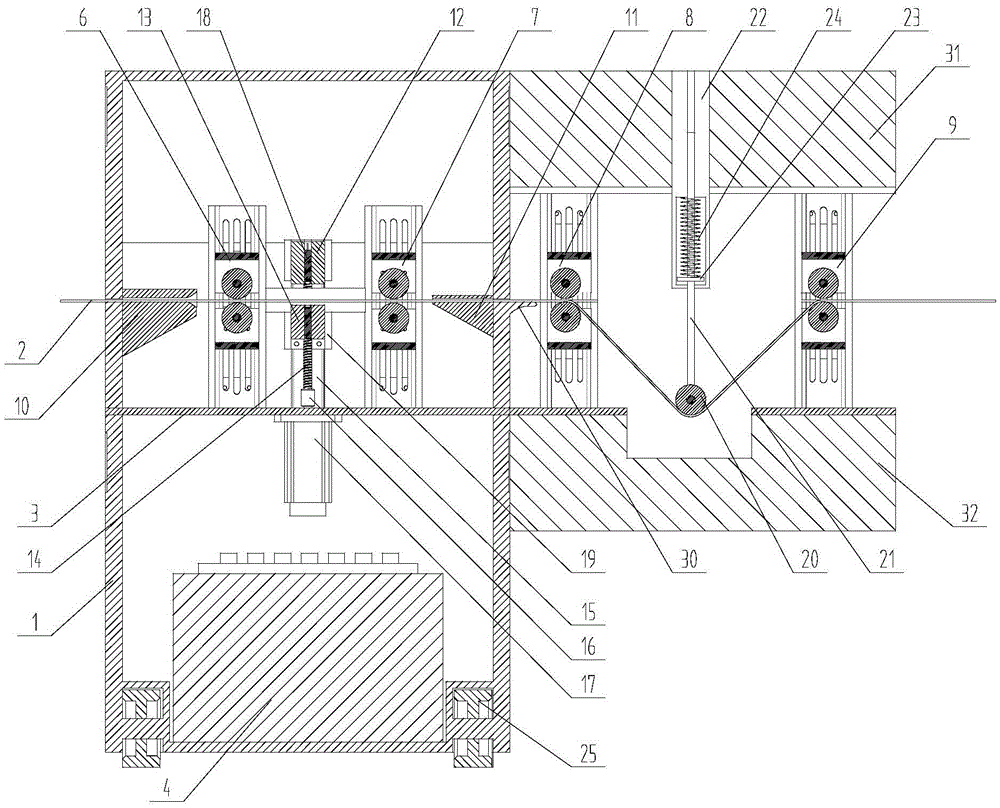
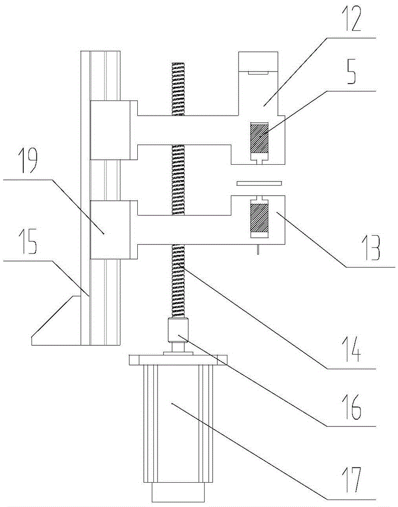
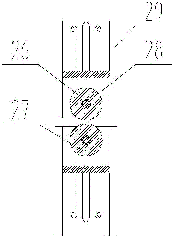
[0032] refer to figure 1 , figure 2 with image 3 As shown, a device capable of continuous on-line detection of steel strip thickness according to the present invention includes a box-type housing 1, a support plate 3, a rechargeable battery 4, a flattening device, a pair of ultrasonic distance sensors 5, four pairs of driving roller groups, and a steel strip Buffer device and pressure detection device, the support plate 3 is arranged horizontally, a part of the support plate 3 is fixed inside the box-type casing 1, and the other part protrudes from one side of the box-type casing 1, and the rechargeable battery 4 is fixed on The bottom plate of the box-type shell 1 provides power for the whole device. The four pairs of driving rollers are respectively located in the first driving roller group 6, the second driving roller group 7, the third driving roller group 8 and the f...


PUM


Abstract

The invention discloses a device being able to continuously detect thickness of a steel belt on line. The device includes a box type housing, a support plate, a rechargeable battery, a pressing device, a pair of ultrasonic distance sensors, four pairs of transmission roller trains, a steel belt buffer unit and pressure detection device, wherein the four pairs of transmission roller trains are respectively a first transmission roller train, a second transmission roller train, a third transmission roller train and a fourth transmission roller train; a left stopper, the first transmission roller train, the pressing device, the second transmission roller train and a right stopper are successively arranged in the horizontal motion direction of the steel belt in the box type housing; and the third transmission roller train, the steel belt buffer unit and the fourth transmission roller train are successively arranged in the horizontal motion direction of the steel belt outside the box type housing. The device being able to continuously detect thickness of a steel belt on line is convenient to move and is simple for operation and detection, and can measuring the thickness of the steel belt during the production process and can conveniently perform data retrieval, thus being very convenient for measuring rolls of steel belts and being suitable for popularization and usage on a large scale.

Description

technical field [0001] The invention relates to the field of detection of steel strip thickness, and more specifically relates to a device capable of continuous on-line detection of steel strip thickness. Background technique [0002] Steel belt refers to the conveyor belt made of carbon steel. The steel belt can be used as the traction and movement construction of the belt conveyor, and it can also be used for bundling goods. A narrow and long steel plate required for mechanical or mechanical products. Steel strip, also known as strip steel, is generally supplied in coils, and has the advantages of high dimensional accuracy, good surface quality, convenience and processing, and material saving. At the same time, the steel strip can be directly rolled to form the basic structure of the shelf, and then spliced ​​into the entire shelf by bolts. . [0003] In the basic construction of steel strip rolling shelves, the shelf factory generally obtains multiple coils of steel str...

Claims


Application Information

Patent Timeline
Patent Type & Authority Applications(China)
IPC IPC(8): G01B17/02
CPCG01B17/02
Inventor 单晓杭余超凡
Owner ZHEJIANG UNIV OF TECH
Why Eureka
Try Eureka