Charging starting debugging method for UPFC serial transformer

A technology of series transformer and debugging method, applied in the direction of instruments, measuring electricity, measuring electrical variables, etc., can solve the problems such as the inability to realize the switching of series transformers, and achieve the effect of effectively carrying out the smooth operation of the project and ensuring the effect of system debugging.

Active Publication Date: 2016-05-25
STATE GRID JIANGSU ELECTRIC POWER CO ELECTRIC POWER RES INST +1
View PDF5 Cites 11 Cited by
  • Summary
  • Abstract
  • Description
  • Claims
  • Application Information

AI Technical Summary

Problems solved by technology

[0006] Due to the particularity of the connection mode of the series transformer in the UPFC system and the way of connecting to the system, the traditional charging start-up method for the transformer (connected to the power grid in parallel) is no longer applicable, mainly reflected in: 1) The low-voltage side of the series transformer is directly connected to the transformer 2) The windings on the high-voltage side of the series transformer are directly connected in series as in the line, and bypass switches are configured on the high-voltage and low-voltage sides. According to its connection mode and operating requirements, The series transformer cannot be connected in series with both the high and low voltage sides open, and the switching of the series transformer from the high voltage side cannot be realized.
In short, the converter valve on the UPFC series side is connected to the power grid through a series transformer. Due to the special connection mode and connection mode of the UPFC system series transformer, the traditional charging and starting debugging method for the transformer (parallel connection to the power grid) is no longer necessary. Applicable, it is not possible to directly conduct charging switching tests on series transformers at rated voltages

Method used


Image

  • Charging starting debugging method for UPFC serial transformer
  • Charging starting debugging method for UPFC serial transformer
  • Charging starting debugging method for UPFC serial transformer

Examples


Embodiment Construction

[0027] In order to make the technical means, creative features, goals and effects achieved by the present invention easy to understand, the present invention will be further described below in conjunction with specific embodiments.

[0028] The series transformer is charged from the low-voltage side and the high-voltage side of the series transformer respectively, and the temporary protection during the charging process is configured.

[0029] First, the low voltage side of the series transformer charges

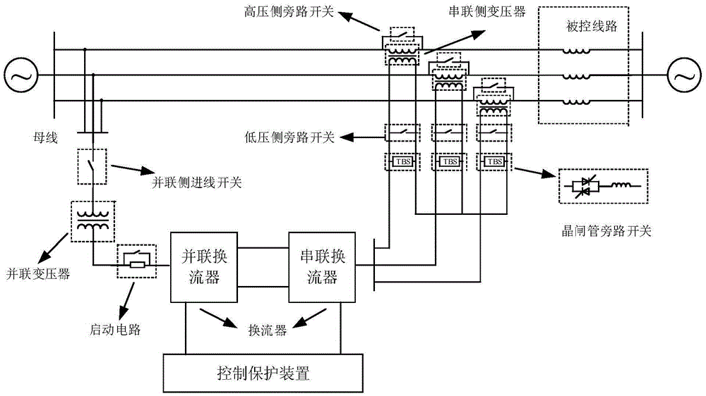
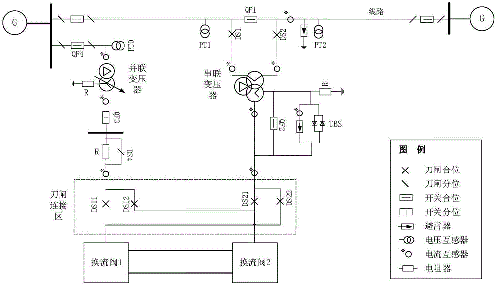
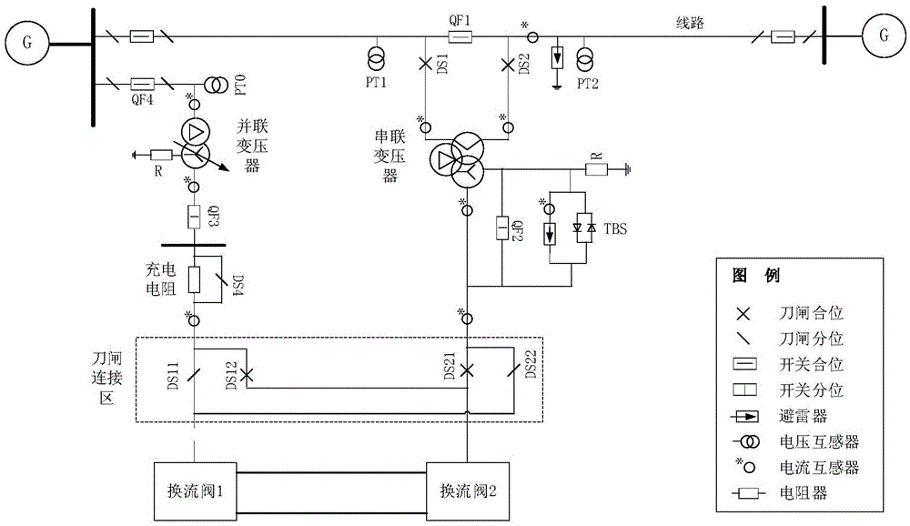
[0030] For the actual UPFC project, in order to give full play to the control performance of the converter valve, a knife switch is configured in the AC switch yard on the valve side so that it has a flexible operation control method. A typical configuration method is: For UPFC projects, generally It also has the function of static synchronous series compensator (SSSC) operation. When a converter in the UPFC system fails, the remaining intact converters can be connected in s...


PUM


Abstract

The invention discloses a charging starting debugging method for a serial transformer of a unified power flow controller (UPFC). The method comprises: (1), a shunt transformer is used as a power supply to carry out a high-voltage side isolation state charging of a series transformer to determine an electromagnetic transient process and a TBS running state of series transformer charging, and voltage nuclear phase and series transformer wiring checking are completed by means of voltage transformer PT charging of a high-voltage side with line bus side of the series transformer and voltage transformer PT charging of a high-voltage side with line outlet side of the series transformer; (2), high-voltage side charging is carried out on the series transformer by a line switch and series transformer protection and load checking are carried out by using line closing-loop currents; (3), low-voltage side charging of the series transformer and high-voltage side charging temporary protection configuration are carried out. According to the invention, charging of a series transformer, a thyristor bypass switch (TBS), and correlated devices as well as nuclear phase and protection checking of the series transformer can be completed.

Description

technical field [0001] The invention relates to a charging start-up debugging method for a UPFC series transformer, belonging to the technical field of power system automation. Background technique [0002] The Unified Power Flow Controller (UPFC) is composed of parallel-side converters and series-side converters. The parallel side can realize active and reactive power adjustment. Active power adjustment is mainly to stabilize the DC capacitor voltage and absorb active power from the grid to compensate the series The active power required by the side and its own active power consumption, and reactive power regulation is to inject reactive power into the system to stabilize the voltage of the access point. The series side regulates the line power flow by controlling its series injection voltage vector. [0003] The UPFC system mainly consists of converters, DC connection lines, series transformers and parallel transformers. The parallel side converters are connected to the p...

Claims


Application Information

Patent Timeline
Patent Type & Authority Applications(China)
IPC IPC(8): G01R31/00
CPCG01R31/00
Inventor 李鹏孔祥平林金娇弓新月黄哲忱高磊袁宇波
Owner STATE GRID JIANGSU ELECTRIC POWER CO ELECTRIC POWER RES INST
Why Eureka
Try Eureka