
Circuit detection method and system

A circuit detection and charge technology, applied in the direction of measuring electricity, measuring devices, measuring electrical variables, etc., can solve the problems of insignificant detection effect, inability to judge whether the two driving lines are short-circuited, etc., to reduce the detection cost, improve the detection sensitivity, Detecting the effect of low cost

Inactive Publication Date: 2016-05-25
CHIPONE TECH BEIJINGCO LTD
View PDF8 Cites 11 Cited by
  • Summary
  • Abstract
  • Description
  • Claims
  • Application Information

AI Technical Summary

Problems solved by technology

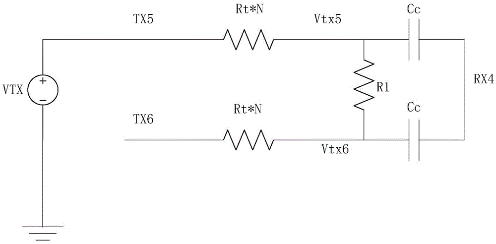
If the short-circuit resistance R1 is large, such as greater than 10KΩ, the amplitude of V1 will change very little, and the amount of charge received by the sensing line RX4 will change very little, making it impossible to judge whether there is a short circuit between the two driving lines
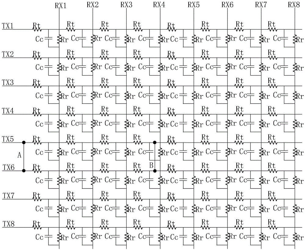
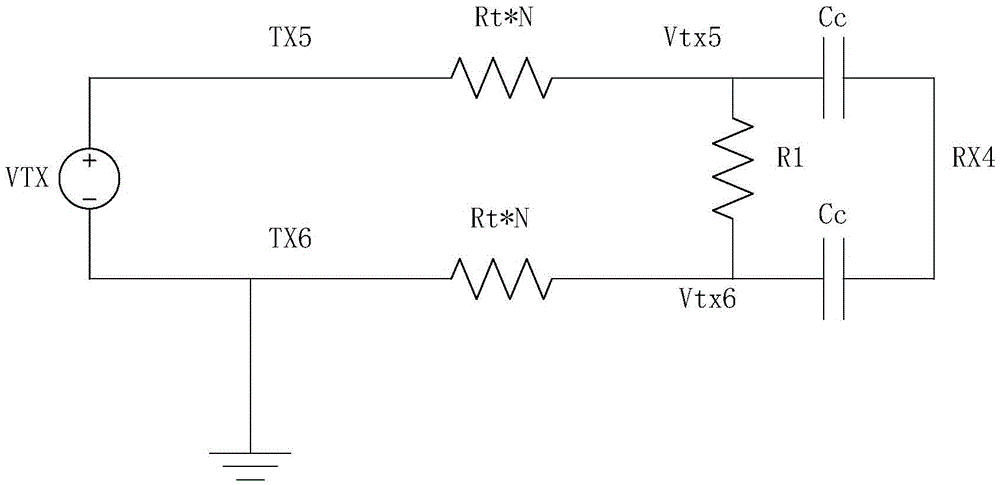
[0008] If the short-circuit position of the driving line TX5 and the driving line TX6 is not at the starting end, namely A, but at the middle or end of the driving line, for example, figure 1 At the position B shown, at this time N=4, then constitute a such as figure 2 The resistors Rt*N, R1, and Rt*N shown in are connected in series, although the voltage at the middle position of the TX6 line will rise, but the voltage at the middle position of the TX5 line will also decrease, and the changes of the two cancel each other out. The detected charge amount (the product of TX voltage and Cc) changes very little, and the detection effect is not obvious

Method used


Image

  • Circuit detection method and system
  • Circuit detection method and system
  • Circuit detection method and system

Examples


Embodiment Construction

[0041] The present invention is described below based on examples, but the present invention is not limited to these examples. In the following detailed description of the invention, some specific details are set forth in detail. The present invention can be fully understood by those skilled in the art without the description of these detailed parts. To avoid obscuring the essence of the present invention, well-known methods, procedures, procedures, and components have not been described in detail.

[0042] Refer below image 3 and Figure 4 Embodiments of the circuit testing method and system of the present invention are described.

[0043] Method example:

[0044] The invention provides a circuit detection method, which is used for detection including a capacitive touch screen. Such as figure 1 As shown, the capacitive touch screen includes multiple driving lines and sensing lines intersecting the multiple driving lines. The driving lines and the sensing lines exist on ...


PUM


Abstract

The invention discloses a circuit detection method and system, mainly for solving the problem of low short-circuit detection sensitivity existing in a conventional touch screen short-circuit detection method. The circuit detection method is applied to detection of a capacitive touch screen and the like, the capacitive touch screen comprises multiple driving lines and an induction line intersected with the multiple driving lines, and capacitive nodes are formed at intersection positions between the driving lines and the induction line. The method comprises the following steps: loading voltages to a driving line to be detected, hanging at least a part of the driving lines besides the driving line to the detected in chip internal paths, detecting an electric parameter on the induction line, and determining whether the driving line to be detected is at a short-circuit state through comparing the detected electric parameter with a set value. According to the circuit detection method provided by the invention, when the driving line to be detected is at the short-circuit state, the electric parameter at the induction line is substantially changed, even short-circuit resistance is quite large, whether the driving line to be detected is at the short-circuit state can still be accurately determined, and thus the detection sensitivity is greatly improved.

Description

technical field [0001] The invention relates to the field of circuit detection, in particular to a circuit detection method and a detection system for a capacitive touch screen. Background technique [0002] Projected capacitance (Projective capacitance) touch screens have been widely used in human-computer interaction interfaces of mobile phones, tablet computers, automatic teller machines and various management systems. Projected capacitive touch screens have the advantages of high light transmittance, wear resistance, and long life. [0003] Projected capacitive touch screens include self capacitance (self capacitance) type capacitive touch screens and mutual capacitance (mutual capacitance) type capacitive touch screens. [0004] In the self-capacitance touch screen, the horizontal and vertical electrode arrays are made of conductive materials such as Indium Tin Oxide (ITO) on the surface of the glass substrate, and other transparent conductive oxides can also be used t...

Claims


Application Information

Patent Timeline
Patent Type & Authority Applications(China)
IPC IPC(8): G01R31/02
CPCG01R31/50
Inventor 曲孔宁
Owner CHIPONE TECH BEIJINGCO LTD
Learn More