Inertial positioning method for real estate field measurement

An inertial positioning and field measurement technology, applied in the field of surveying and mapping, can solve the problems that cannot be directly measured and cannot be vertically aligned with the measurement center reference of the inertial positioning equipment, the vertical alignment of the measurement center of the positioning equipment, and the increase of inertial positioning errors with time. Positioning error, fast measurement, and the effect of improving measurement efficiency

Inactive Publication Date: 2016-05-25
SOUTHEAST UNIV
View PDF7 Cites 1 Cited by
  • Summary
  • Abstract
  • Description
  • Claims
  • Application Information

AI Technical Summary

Problems solved by technology

[0004] The present invention aims at the inherent defects in the application of inertial positioning equipment to real estate field measurement, that is, the inertial positioning error increases with time and cannot directly measure the point to be measured that cannot be vertically aligned with the measurement center reference of inertial positioning equipment, and proposes a real estate field-oriented The inertial positioning method of measurement, by collecting the static measurement process data of the known point and the point to be measured, performs two initial alignments, and then performs two-way time strapdown calculation on the dynamic measurement process data during the journey, and obtains the forward and reverse directions. The coordinates of the points to be measured are calculated on the basis of the strapdown solution position information; for the points to be measured that cannot be vertically aligned with the measurement center of the inertial positioning equipment, the measurement is completed by transferring the measurement reference located in the center of the chassis to the corners of the chassis

Method used


Image

  • Inertial positioning method for real estate field measurement
  • Inertial positioning method for real estate field measurement
  • Inertial positioning method for real estate field measurement

Examples


Embodiment Construction

[0037] The specific implementation manners of the present invention will be further described below in conjunction with the accompanying drawings.

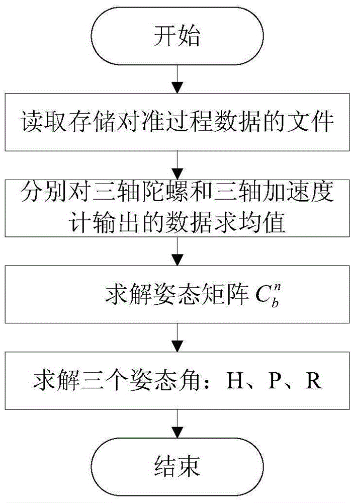
[0038] The core component of the inertial positioning equipment in this embodiment—the inertial sensor is composed of a fiber optic gyroscope and a quartz flexible accelerometer. The data acquisition and processing module selects a PC / 104 industrial computer, and the data output by the inertial sensor is collected and stored in a memory card. The computer controls the PC / 104 industrial control computer to start or stop collecting and storing data through Bluetooth.

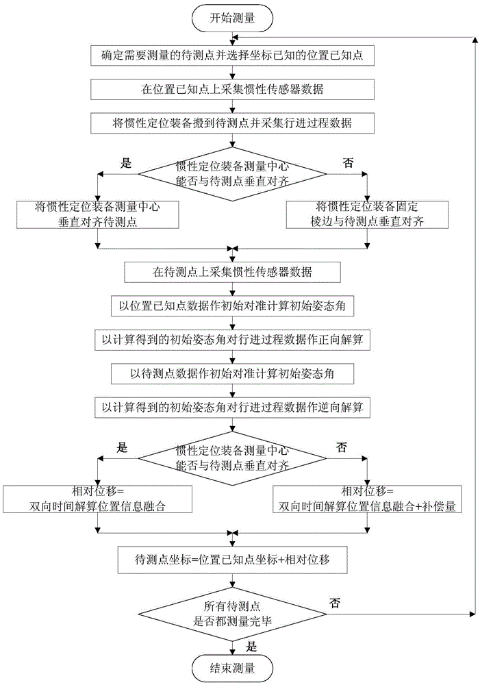
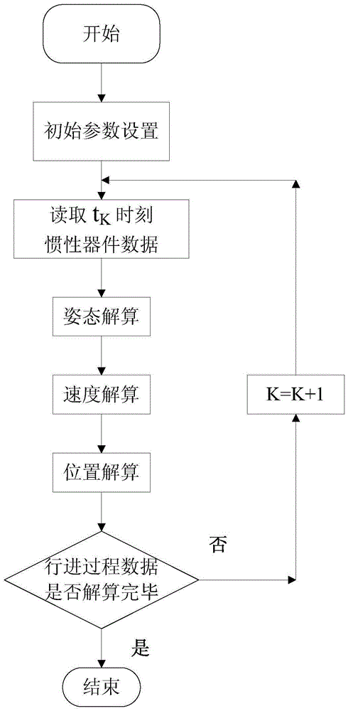
[0039] Such as figure 1 As shown, the present invention is oriented to the inertial positioning method measurement process of real estate on-the-spot measurement as follows:

[0040] (1) Determine the point to be measured and the point with known position: determine a point to be measured that needs to be measured in the operation area, select a point with a good GPS...


PUM


Abstract

The invention discloses an inertial positioning method for real estate field measurement. The method comprises: by acquiring and storing the static measurement process data of a point with a known position and a to-be-measured point, performing twice initial alignment , further performing two-way time strapdown calculation of ongoing dynamic measurement process data, carrying out position fusion on the basis of inverse strapdown calculation of the position information, and obtaining the coordinate of the to-be-measured point; for the to-be-measured point which cannot be vertically aligned with the measurement center of an inertial positioning device, transmitting the measuring basis located at the cabinet center to the cabinet edge so as to finish the measurement. By means of the invention, the positioning error of the to-be-measured point which is caused by the inertial positioning device is well modified, the measurement precision is improved, and it is possible to measure the to-be-measured point which cannot be vertically aligned with the measurement center of the inertial positioning device.

Description

technical field [0001] The invention belongs to the technical field of surveying and mapping, and relates to surveying, surveying and mapping technology and strapdown inertial positioning technology, in particular to an inertial positioning method for real estate field measurement. Background technique [0002] At present, the conventional real estate field measurement method uses GPS-RTK and total station as the main measurement equipment, but when GPS-RTK technology is used for detailed measurement, the satellite signal is easily blocked by buildings and structures and cannot be positioned; when using When using a total station, for the points to be measured with poor visibility conditions, that is, when there is an obstruction on the connection between the target to be observed and the total station, the total station cannot measure data due to poor observation conditions , At this time, only a steel ruler can be used for measurement, resulting in low efficiency and low a...

Claims


Application Information

Patent Timeline
Patent Type & Authority Applications(China)
IPC IPC(8): G01S19/49G01C21/16
CPCG01S19/49G01C21/165
Inventor 吴峻施成功暴旭凯张健闫晶蒋晨瑶冯家政
Owner SOUTHEAST UNIV
Why Eureka
Try Eureka