
Fuel cell system and method for discharging fluid in the system

A fuel cell system and fuel cell technology, which are applied in the fields of fuel cells, fuel cell additives, electrolyte treatment of solid electrolyte batteries, etc., can solve the problems of insufficient drainage treatment, unable to ensure starting characteristics, etc., and achieve the effect of sufficient drainage treatment.

Active Publication Date: 2016-05-25
TOYOTA JIDOSHA KK
View PDF10 Cites 17 Cited by
  • Summary
  • Abstract
  • Description
  • Claims
  • Application Information

AI Technical Summary

Problems solved by technology

Insufficient drainage treatment in this way may cause the residual water to freeze in a sub-freezing environment, making it impossible to ensure start-up performance.

Method used


Image

  • Fuel cell system and method for discharging fluid in the system
  • Fuel cell system and method for discharging fluid in the system
  • Fuel cell system and method for discharging fluid in the system

Examples


Embodiment Construction

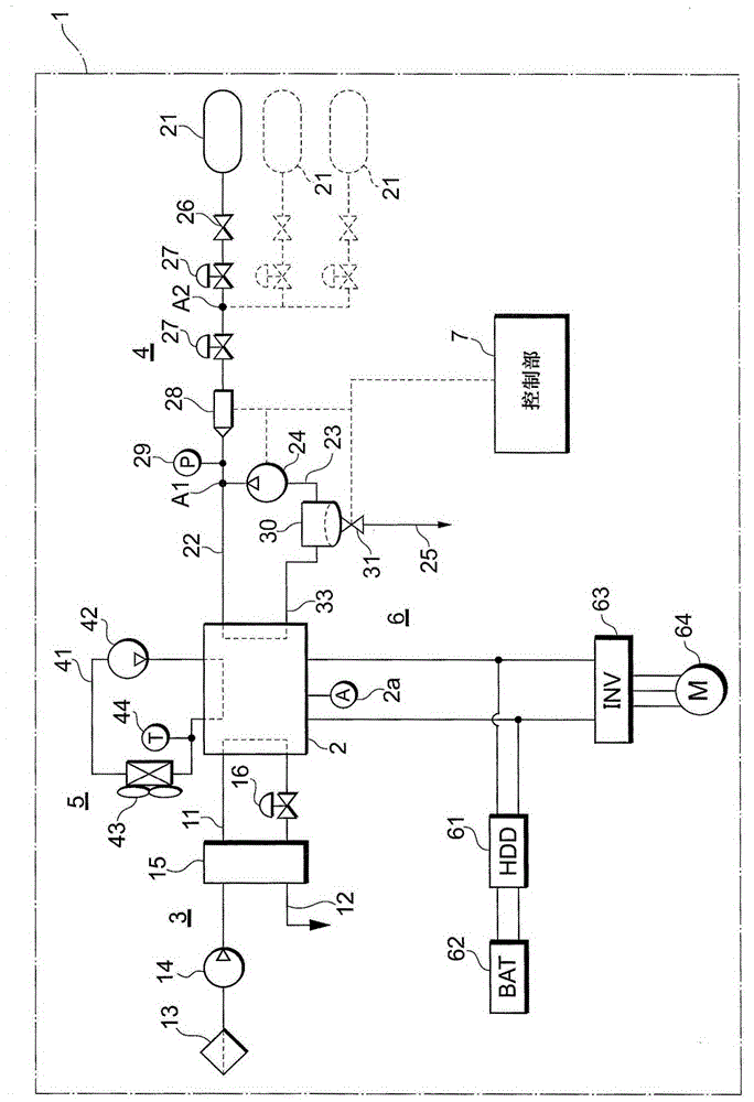
[0037] The configuration of the present invention will be described in detail based on an example of embodiment shown in the drawings. Hereinafter, first, the overall configuration of the fuel cell system 1 will be described, and then, the fluid discharge process of the fuel cell system 1 will be described.

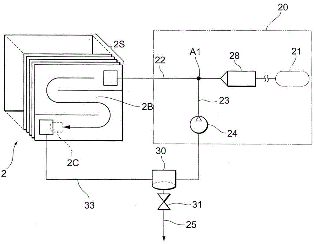
[0038] figure 1 A schematic configuration of a fuel cell system 1 mounted on a fuel cell vehicle is shown, figure 2 The schematic structure of the hydrogen off-gas circulation flow path is shown. It should be noted that an example of a system that can be applied as a vehicle-mounted power generation system of a fuel cell vehicle (FuelCellHybridVehicle) is shown here, but the above-mentioned fuel cell system 1 can also be used as a etc.) or a self-propelled structure such as a robot or a fixed power generation system.

[0039] The fuel cell system 1 of the present embodiment includes: a fuel cell 2 that generates electric power through an electrochemical reaction by re...


PUM


Abstract

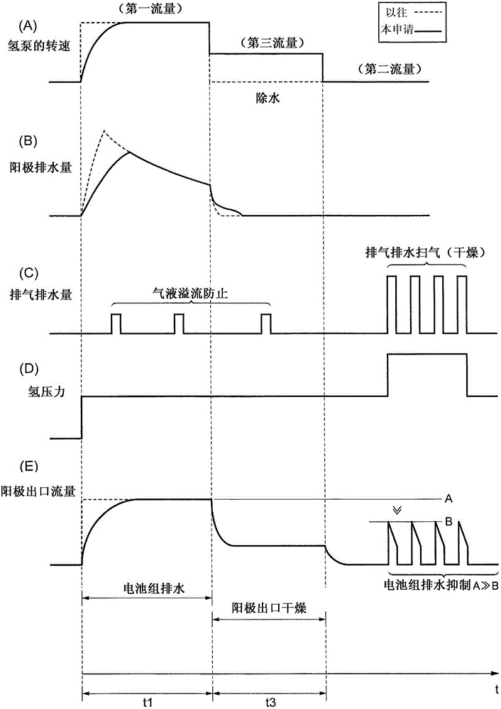
There is provided a fuel cell system, wherein a controller configured to set the flow volume of a fluid in an anode flow path at an outlet of an anode of the fuel cell to a first flow volume, then set thereafter the flow volume of the fluid in the anode flow path at the outlet of the anode to a second flow volume which is smaller than the first flow volume, and discharge the water in the hydrogen discharge flow path by opening an exhaust and drain valve while the fluid is flowing at the second flow volume.

Description

technical field [0001] The present invention relates to a fuel cell system and a method for discharging fluid in the system. Background technique [0002] Impurities such as nitrogen and / or carbon monoxide and / or water accumulate in the inside of the fuel cell system and / or in the circulation flow path of the fuel off-gas due to power generation. In order to discharge such impurities and / or water to the outside, an exhaust and drain valve is installed on the discharge channel connected to the circulation channel, and by controlling the opening and closing of the exhaust and drain valve, the gas in the circulation channel is and / or technology in which water is expelled at regular intervals (exile technology). [0003] In addition, in order to ensure the starting performance of the fuel cell system at the freezing point, immediately before components (such as the above-mentioned exhaust and drain valves) constituting the fuel cell system reach 0°C, the gas stored in the flow ...

Claims


Application Information

Patent Timeline
Patent Type & Authority Applications(China)
IPC IPC(8): H01M8/04119H01M8/04746
CPCH01M8/04156H01M8/04179H01M8/04253H01M8/04753H01M8/04761H01M8/04291Y02E60/50H01M8/04097H01M8/04201H01M8/0432H01M8/04402
Inventor 户井田政史长沼良明小川朋宏
Owner TOYOTA JIDOSHA KK
Learn More