Dehumidification system

A humidity and humidity value technology, which is applied in the direction of electrical components, cooling/ventilation of substation/switchgear, details of substation/switch layout, etc., can solve electrical breakdown, components are susceptible to moisture, and substation equipment refuses to move or disturb And other issues

Inactive Publication Date: 2016-05-25
STATE GRID ZHEJIANG NINGBO FENGHUA POWER SUPPLY CO LTD +2
View PDF5 Cites 0 Cited by
  • Summary
  • Abstract
  • Description
  • Claims
  • Application Information

AI Technical Summary

Problems solved by technology

[0003] The components in the control box of the substation equipment are prone to moisture when the weather changes, which will cause the rotating part of the substation equipment to fail when performing work, the insulation resistance will drop, resulting in electrical breakdown, and the secondar

Method used


Image

  • Dehumidification system

Examples


Embodiment

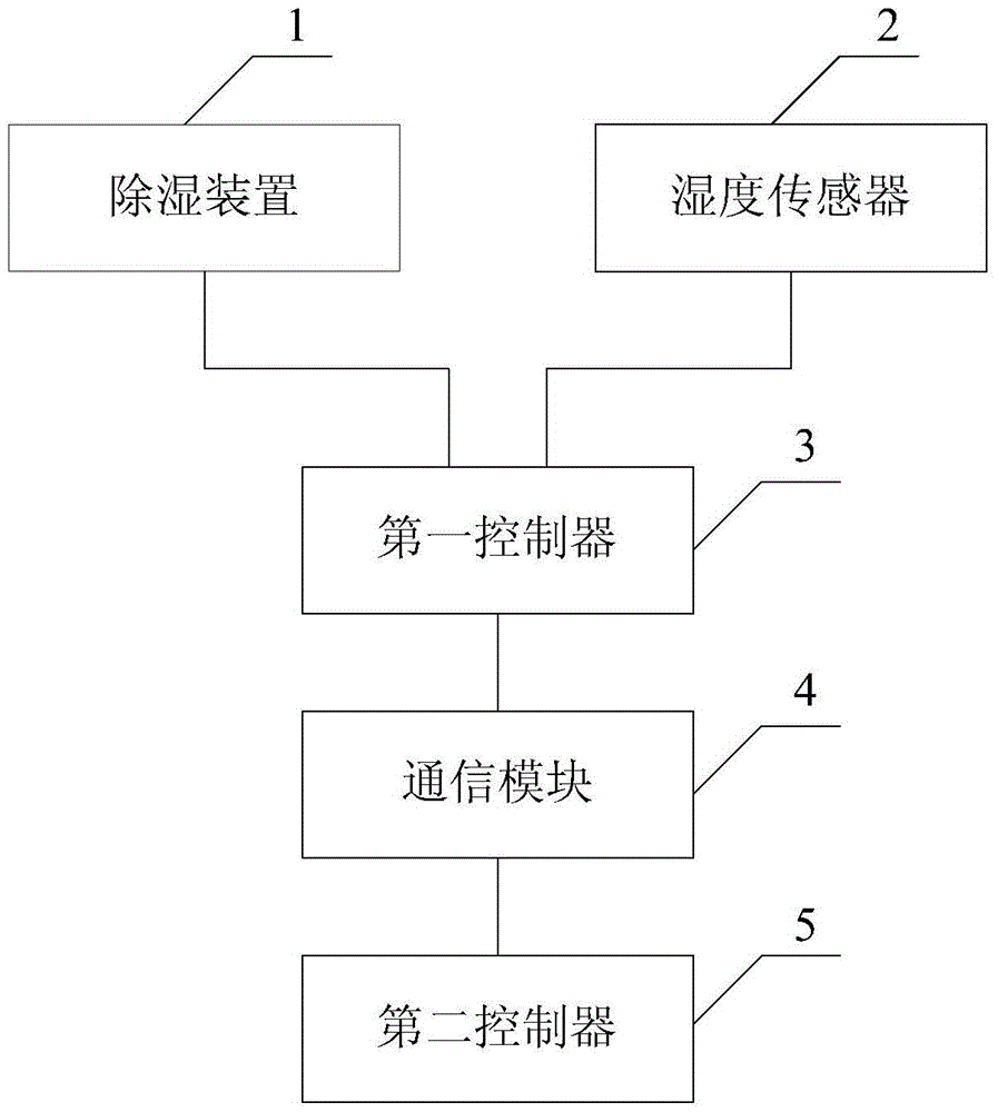
[0031] figure 1 It is a schematic structural diagram of a dehumidification system provided in an embodiment of the present application.

[0032] Such as figure 1 As shown, the dehumidification system includes:

[0033] Dehumidification device 1;

[0034] A humidity sensor 2 for detecting the humidity value of the gas in the control box;

[0035] A first controller 3 connected to the dehumidification device 1 at one end and connected to the humidity sensor 2 at the other end;

[0036] A communication module 4 connected to the first controller 3;

[0037] Connected with the communication module 4, it is used to control the second controller 5 of the corresponding dehumidification device to adjust the humidity of the gas in the control box by using the humidity value detected by the humidity sensor.


PUM


Abstract

The invention provides a dehumidification system. A gas humidity value in a control box is detected by a humidity sensor; the humidity value detected by the humidity sensor is transmitted to a second controller by a first controller via a communication module, so that the second controller controls a corresponding dehumidification apparatus to adjust the gas humidity in the control box based on the humidity value so as to realize control for the gas drying degree in the control box of power transformation equipment. The problem of frequent power grid accidents caused by influenced safe operation of the power transformation equipment due to that components and parts are affected with damp easily in the control box is avoided.

Description

technical field [0001] The present invention relates to the technical field of electric equipment, and more specifically, relates to a dehumidification system. Background technique [0002] Various electronic components are installed in the control boxes of power transformation equipment such as high-voltage cabinets, indoor / outdoor switches, knife control boxes, and power boxes to realize various control and execution functions. In order to ensure the reliability of the use and service life of the substation equipment, the control box of this type of substation equipment has strict requirements on the dryness of the working environment. [0003] The components in the control box of the substation equipment are prone to moisture when the weather changes, which will cause the rotating part of the substation equipment to fail when performing work, the insulation resistance will drop, resulting in electrical breakdown, and the secondary terminals may be poorly connected or shor...

Claims


Application Information

Patent Timeline
IPC IPC(8): H02B1/56
CPCH02B1/565
Inventor 孙益辉舒戴龙魏亚瑟陈骥翔
Owner STATE GRID ZHEJIANG NINGBO FENGHUA POWER SUPPLY CO LTD
Why Eureka
Try Eureka