Liquid trap of rectification tower

A rectification tower and liquid collection technology, which is applied in the field of rectification tower liquid collection devices, can solve the problems of unsuitable installation of redistributors in rectification towers, uncontrollable wall flow phenomenon of rectification towers, and reduced overall performance of rectification towers. , to achieve the effect of low manufacturing cost, simple design and guaranteed stability

Inactive Publication Date: 2016-06-01
TIANJIN HEAD HAOTIAN TECH DEV CO LTD
View PDF1 Cites 4 Cited by
  • Summary
  • Abstract
  • Description
  • Claims
  • Application Information

AI Technical Summary

Problems solved by technology

[0002] In the field of chemical industry, the rectification tower is an important means of purifying chemical components. When the rectification tower is in use, the steam enters the tower from the bottom of the tower, and the mixed liquid enters the tower from the feed port of the rectification tower. and the decline of the mixed liquid, the gas-liquid two-phase countercurrent contact is completed for interphase mass transfer, that is, the low boiling point components in the mixed liquid are continuously transferred to the steam, and the high boiling point components in the steam are continuously transferred to the descending liquid, rectification The tower tends to generate wall flow during the rectification process, so in the prior art, a redistributor is installed in the rectification tower to collect the wall flow and redistribute it evenly into the tower, but the rectification tower with a smaller diameter is not suitable for installation Redistributor, and then lead to the uncontrollable wall flow phenomenon of small-scale rectification tower, make the liquid reflux flow on packing reduce, and then reduce the purity of rectification product; A baffle is installed in the small tower as a liquid collector to collect the liquid in the wall flow, but the baffle liquid collector has a funnel-shaped structure, which makes it difficult to evenly distribute the wall flow into the tower again, thus reducing the rectification efficiency. The overall performance of the tower, so the technicians developed a liquid collector that is more suitable for the rectification tower. To solve this problem, the liquid collector includes a liquid collection tank surrounded by an inner ring wall, an outer ring wall and a bottom plate, and a number of openings are arranged on the bottom plate, and the inner ring wall is close to the lower part of the bottom plate along the radial direction. There are several first overflow holes, and some second overflow holes are arranged in the middle along the radial direction. This liquid collector solves the wall flow problem of the small rectification tower to a certain extent, but its disadvantage is that the outer ring The wall occupies a certain amount of space, so when the amount of liquid that is going down is large, the descending liquid flows down from the middle of the liquid collector, so it is still not possible to uniformly carry out the interphase mass transfer of the gas-liquid two-phase in the entire rectification column

Method used


Image

  • Liquid trap of rectification tower
  • Liquid trap of rectification tower

Examples


Embodiment Construction

[0024] Specific embodiments of the present invention will be described in detail below in conjunction with the accompanying drawings.

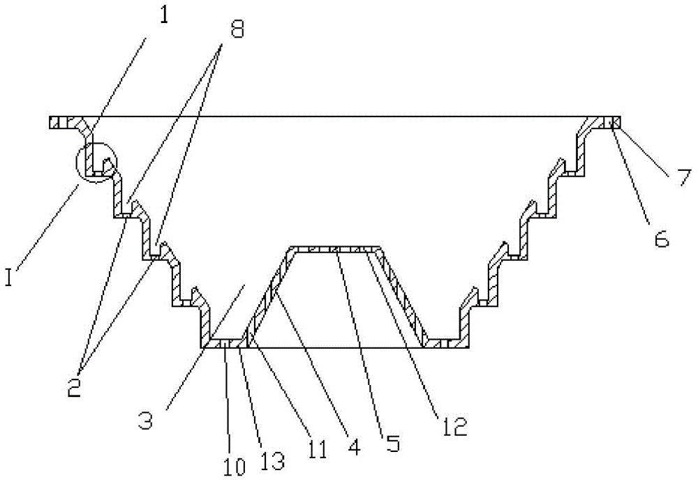
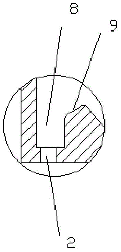
[0025] Such as figure 1 , figure 2 As shown, the rectifying tower liquid collection device includes an outer ring wall 1 and an inner ring wall 4, the height of the outer ring wall 1 is greater than the height of the inner ring wall 4, and the diameter of the top of the outer ring wall 1 is greater than that of the bottom end diameter, the top diameter of the inner ring wall 4 is smaller than the bottom end diameter, the bottom of the inner ring wall 4 and the bottom of the outer ring wall 1 are horizontally connected with a bottom plate 13, and the top of the inner ring wall 4 is horizontally provided with a top plate 5, the The outer ring wall 1, the bottom plate 13 and the inner ring wall 4 form the second liquid collection tank 3, and the outer ring wall 1, the inner ring wall 4, the bottom plate 13 and the top plate 5 form a liquid coll...


PUM


Abstract

The invention provides a liquid trap of a rectification tower. The liquid trap comprises an outer annular wall and an inner annular wall, wherein a base plate is horizontally connected between the bottom of the inner annular wall and the bottom of the outer annular wall; the top of the inner annular wall is horizontally provided with a top plate; the outer annular wall, the base plate and the inner annular wall form a second liquid trapping groove; the outer annular wall, the inner annular wall, the base plate and the top plate form a liquid trapping cavity; the inner side of the outer annular wall is provided with a plurality of annular first liquid trapping grooves from top to bottom; the plurality of first liquid trapping grooves are respectively horizontally formed and are distributed in the outer annular wall in a stepped mode; the groove bottoms of the first liquid trapping grooves are horizontally formed; the groove openings of the first liquid trapping grooves are vertically upward; the bottom of each first liquid trapping groove is vertically provided with a plurality of first holes; the base plate is vertically provided with a plurality of second holes, and the second holes are uniformly formed; the inner annular wall is provided with a plurality of third holes which are used for communicating the liquid trapping cavity and the exterior; and the top plate is vertically provided with a plurality of fourth holes.

Description

technical field [0001] The invention belongs to the field of rectification tower equipment, in particular to a rectification tower liquid collection device. Background technique [0002] In the field of chemical industry, the rectification tower is an important means of purifying chemical components. When the rectification tower is in use, the steam enters the tower from the bottom of the tower, and the mixed liquid enters the tower from the feed port of the rectification tower. and the decline of the mixed liquid, the gas-liquid two-phase countercurrent contact is completed for interphase mass transfer, that is, the low boiling point components in the mixed liquid are continuously transferred to the steam, and the high boiling point components in the steam are continuously transferred to the descending liquid, rectification The tower tends to generate wall flow during the rectification process, so in the prior art, a redistributor is installed in the rectification tower to ...

Claims


Application Information

Patent Timeline
Patent Type & Authority Applications(China)
IPC IPC(8): B01D3/14B01D3/32
Inventor 郭金灿
Owner TIANJIN HEAD HAOTIAN TECH DEV CO LTD
Why Eureka
Try Eureka