Air laid machine

A web forming machine and air flow technology, applied in textiles, papermaking, non-woven fabrics and other directions, can solve the problem that the uniformity effect is not enough to reflect the uniform weight of fiber and cotton mesh layers.

Inactive Publication Date: 2016-06-01
SUZHOU VOCATIONAL UNIV
View PDF16 Cites 13 Cited by
  • Summary
  • Abstract
  • Description
  • Claims
  • Application Information

AI Technical Summary

Problems solved by technology

Taking the aforementioned CN2663451Y and CN102373516B as examples, since the thickness of the fiber cotton web layer tends to be uniform through the suction of the dust cage, that is, the cotton pressing roller, it is essentially a measure that trea

Method used


Image

  • Air laid machine
  • Air laid machine
  • Air laid machine

Examples


Embodiment Construction

[0027] In order to enable the examiners of the patent office, especially the public, to understand the technical essence and beneficial effects of the present invention more clearly, the applicant will describe in detail the following in the form of examples, but none of the descriptions to the examples is an explanation of the solutions of the present invention. Any equivalent transformation made according to the concept of the present invention which is merely formal but not substantive shall be regarded as the scope of the technical solution of the present invention.

[0028] In the following descriptions, all concepts involving up, down, left, right, front and rear directionality or azimuth are for the position state of the picture being described, and the purpose is to facilitate the public’s understanding. Therefore, it cannot be understood as a special limitation on the technical solution provided by the present invention.

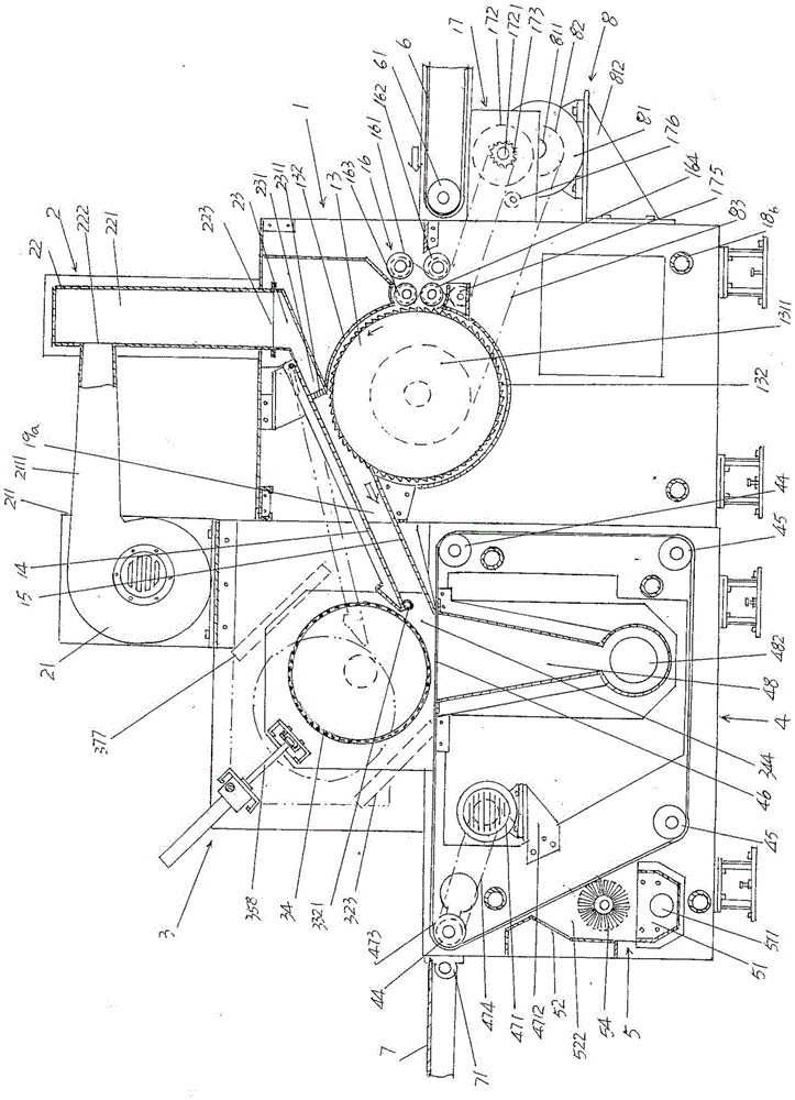
[0029] See figure 1 , provides a cotton feed...


PUM


Abstract

The invention discloses an air laid machine and belongs to the technical field of non-woven fabric machinery. The air laid machine comprises a cotton feeding mechanism and an airflow uniformizing mechanism connected with the cotton feeding mechanism. A cotton pressing mechanism is stacked on a web forming mechanism, and the web forming mechanism and the cotton pressing mechanism are supported by a terrace or a foundation with the terrace as the carrier at the left side of the cotton feeding mechanism. The airflow uniformizing mechanism comprises a set of draught fans, an air bellow and an air bellow air outlet channel, wherein the draught fans are installed on the upper portion of the rear side of the cotton pressing mechanism at intervals, an air outlet of each draught fan is connected with one end of an air outlet pipe of the corresponding draught fan, the other end of the air outlet pipe of each draught fan is connected with an air inlet of the air bellow, the air bellow is connected with the cotton feeding mechanism at the position corresponding to the top of the cotton feeding mechanism, the air bellow air outlet channel is formed after an air outlet in the bottom of the air bellow extends, and an air channel outlet of the air bellow air outlet channel extends to the cotton feeding mechanism. The air laid machine has the advantage that due to the fact that an airflow uniformizing plate is arranged in the air bellow air outlet channel and located at the position corresponding to the air channel outlet, the fiber uniformizing effect is improved, and it is ensured that the thickness of a cellucotton web layer is uniform.

Description

technical field [0001] The invention belongs to the technical field of non-woven machinery, and in particular relates to an air-laid machine. Background technique [0002] The function of the air-laid machine is to form a cotton web from the non-woven fibers opened by the previous process, and transport it to the subsequent shaping equipment (ie non-woven product forming equipment such as needle punching machine, hydroentanglement machine and press machine, etc. ) made of non-woven fabrics, thermal insulation materials, sound insulation blankets, automotive interior parts, home bedding products such as cushions, etc. [0003] The air-laid machine uses a high-speed rotating carding roller to disperse the non-woven fibers in the air field while carding the non-woven fibers and make the non-woven fibers in a three-dimensional distribution state, that is, to form a basically non-oriented state. Because air-laid has wide adaptability to fibers (such as polypropylene fiber, polye...

Claims


Application Information

Patent Timeline
IPC IPC(8): D04H1/732
CPCD04H1/732
Inventor 朱学超刘旭刘殿峰张晓波顾丽亚张永康张义平
Owner SUZHOU VOCATIONAL UNIV
Why Eureka
Try Eureka