Fiber carding and outputting device for air laid machine

A technology of output device and web forming machine, which is applied in the direction of fiber processing safety device, fiber processing, fiber feeding, etc., can solve the problems of invasion, increase the working intensity of equipment management personnel, safety, etc., achieve uniform thickness and reduce maintenance The effect of working intensity and ensuring safety

Inactive Publication Date: 2016-06-01
SUZHOU VOCATIONAL UNIV
View PDF15 Cites 4 Cited by
  • Summary
  • Abstract
  • Description
  • Claims
  • Application Information

AI Technical Summary

Problems solved by technology

Taking the aforementioned CN2663451Y and CN102373516B as examples, since the thickness of the fiber cotton web layer tends to be uniform through the suction of the dust cage, that is, the cotton pressing roller, it is essentially a measure that treats the surface rather than the root cause. On the premise that the previous fiber carding and output are not enough to ensure the fiber uniform effect, the suction of the subsequent station does not really achieve the consistent weight of the fiber cotton layer
[0009] In addition, the roller mechanism and the rolle

Method used


Image

  • Fiber carding and outputting device for air laid machine
  • Fiber carding and outputting device for air laid machine

Examples


Example Embodiment

[0025] In order to enable the public to understand the technical essence and beneficial effects of the present invention more clearly, the applicant will describe in detail in the form of examples below, but the description of the examples is not a limitation to the solution of the present invention. All equivalent transformations that are merely formal rather than substantive should be regarded as the technical solution scope of the present invention.

[0026] In the following description, all the concepts related to the directionality or orientation of up, down, left, right, front and back are aimed at figure 1 The position state shown is for the purpose, so it cannot be understood as a special limitation to the technical solution provided by the present invention.
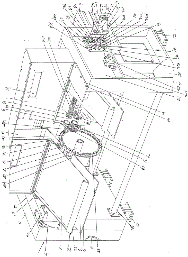
[0027] See figure 1 , A rack 1 is given. The rack 1 consists of a left wall panel 11, a right wall panel 12, a pair of wall panel supporting and fixing beams 13a and a pair of wall panel lower supporting and fixing pi...


PUM


Abstract

A fiber carding and outputting device for an air laid machine comprises a machine frame, a cotton pressing plate supported by a left wallboard and a right wallboard, an air bellow fixed between the left wallboard and the right wallboard, a cotton carding roller supported between the left wallboard and the right wallboard, a cotton supporting plate arranged under the cotton pressing plate correspondingly, and a roller mechanism supported between the left wallboard and the right wallboard and connected with a roller driving mechanism. The device is characterized in that an air outlet channel of the air bellow extends to a cotton outlet of the cotton carding roller and is connected with the front side of a guide plate on the cotton carding roller, and an airflow uniformizing plate is arranged at the position of an air outlet of the air outlet channel of the air bellow; the roller device comprises a large upper roller, a large lower roller, a small upper roller, a small lower roller and a pair of roller shaft adjusting bases, and the roller driving mechanism comprises a driving motor fixing base, a driving motor, a driving motor chain wheel, a large upper roller shaft chain wheel, a large lower roller shaft chain wheel, a small upper roller shaft chain wheel, a small lower roller shaft chain wheel, a transition tensioning chain wheel, a tensioning chain wheel and a driving chain. By the adoption of the device, it is ensured that the thickness of a non-woven cellucotton web layer is uniform, work strength is reduced, and safety is guaranteed.

Description

technical field [0001] The invention belongs to the technical field of non-woven machinery, and in particular relates to a fiber carding and output device of an air-laid machine. Background technique [0002] The function of the air-laid machine is to form a cotton web from the non-woven fiber loosened by the opening device in the previous process, that is, the opening machine, and transport it to the shaping equipment in the subsequent process to shape it into such things as non-woven fabrics, thermal insulation materials, and sound insulation felts. , automotive interior parts, home bedding products (such as cushions) and other products. The aforementioned sizing equipment such as acupuncture machines and hydroentanglement machines. [0003] It can be seen from the above that the air-laid machine is located between the opening device and the setting equipment on the complete non-woven product production line. The air-laid machine uses a high-speed rotating carding roller...

Claims


Application Information

Patent Timeline
IPC IPC(8): D01G25/00D01G31/00D01G23/02D04H1/732
CPCD01G23/02D01G25/00D01G31/00D04H1/732
Inventor 张义平杜洁赵海燕刘殿峰周正存张晓波张永康朱学超顾丽亚
Owner SUZHOU VOCATIONAL UNIV
Why Eureka
Try Eureka