Optical fiber aging performance test system
A technology of aging performance and testing system, which is applied in the direction of optical instrument testing, testing of optical fiber/optical waveguide equipment, testing of machine/structural components, etc. It can solve problems such as damage to electronic equipment, affecting the accuracy of actual testing, and attenuation of process effects. To achieve the effect of improving accuracy, improving convenience and effectiveness, and increasing coordination effect
- Summary
- Abstract
- Description
- Claims
- Application Information
AI Technical Summary
Problems solved by technology
Method used
Image
Examples
Embodiment 1
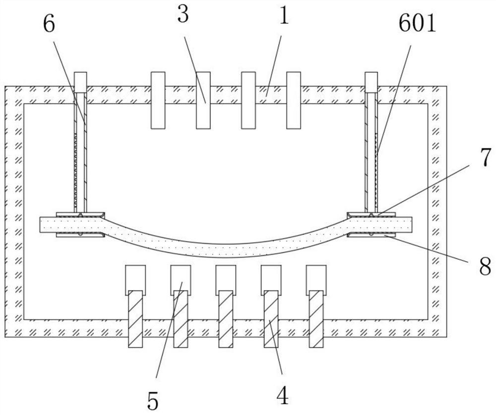
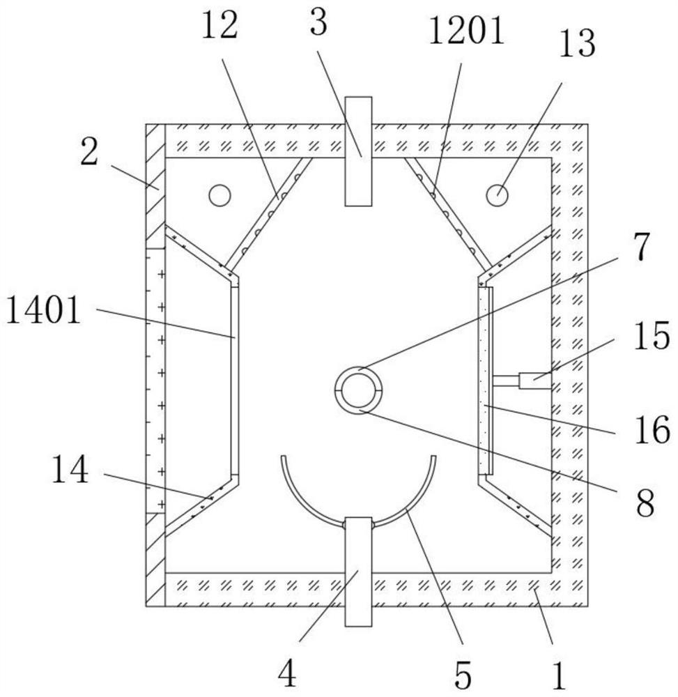
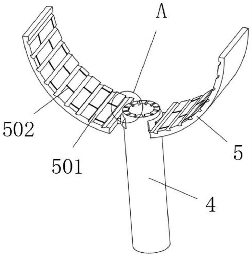
[0036] refer to Figure 1-6 , a kind of optical fiber aging performance testing system, comprises test box 1, and one end of test box 1 is provided with box door 2, and the middle position of box door 2 is provided with visible window, and both sides inside test box 1 are all provided with fixing mechanism, And the optical fiber cable to be tested is detachably connected between the two fixing mechanisms, the length of the middle position of the optical fiber cable to be tested is greater than the distance between the two fixing mechanisms, a temperature control mechanism is arranged in the test box 1, and the top of the test box 1 A plurality of spray pipes 3 are fixed in the middle of the inner wall, and the spray pipes 3 spray water mist downwards, and a plurality of aeration pipes 4 are fixed in the middle of the inner wall of the bottom of the test chamber 1, and the aeration pipes 4 blow up deuterium Gas, the spray pipe 3 and the aeration pipe 4 circulate at intervals; ...
Embodiment 2
[0052] Embodiment 2 includes all structure and method parts of embodiment 1, with reference to Figure 1-8 , an optical fiber aging performance testing system, also includes, the inner walls of both ends of the test box 1 are fixed with a fixed frame 14, and the middle position of the fixed frame 14 is provided with through grooves 1401 distributed equidistantly in the horizontal direction, and the test box 1 is far away from the One end inner wall of box door 2 is fixed with cylinder 15, and cylinder 15 is fixed with installation plate near one end of fixed frame 14, and the position corresponding to the outer wall of one end of fixed frame 14 of mounting plate and through slot 1401 is fixed with movable part 16, and the outer wall of movable part 16 Slidingly connected with the inner wall of the groove 1401;
[0053] The outer wall of one end of the movable part 16 away from the mounting plate is provided with airflow grooves 1601 distributed equidistantly in the vertical di...
PUM
 Abstract
Description
Claims
Application Information
 - R&D
- Intellectual Property
- Life Sciences
- Materials
- Tech Scout
- Unparalleled Data Quality
- Higher Quality Content
- 60% Fewer Hallucinations
Browse by: Latest US Patents, China's latest patents, Technical Efficacy Thesaurus, Application Domain, Technology Topic, Popular Technical Reports.
© 2025 PatSnap. All rights reserved.Legal|Privacy policy|Modern Slavery Act Transparency Statement|Sitemap|About US| Contact US: help@patsnap.com


