
Antique corridor water saving structure

A technology for corridors and water collection tanks, which is applied in general water supply conservation, water supply installations, drinking water installations, etc., and can solve problems such as no water-saving installations, inability to comprehensively utilize rainwater, and waste of water resources

Inactive Publication Date: 2016-06-01
SHAANXI DONGXIAN YONGYI ELECTROMECHANICAL TECH
View PDF0 Cites 0 Cited by
  • Summary
  • Abstract
  • Description
  • Claims
  • Application Information

AI Technical Summary

Problems solved by technology

[0002] At present, antique corridors generally do not have water-saving devices, and rainwater cannot be comprehensively utilized, resulting in waste of water resources

Method used


Image

  • Antique corridor water saving structure

Examples


Embodiment Construction

[0008] The present invention will be described in detail below in conjunction with the accompanying drawings.

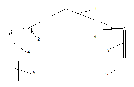
[0009] Referring to the accompanying drawings, an antique corridor water-saving structure includes a first water collection tank 2 and a second water collection tank 3 connected on both sides of the antique corridor roof 1, and the first water collection tank 2 passes through the first water collection pipe 4 and the first water collection tank. The pool 6 is connected, and the second sump 3 is connected with the second sump 7 through the second sump 5 .

[0010] Working principle of the present invention is:

[0011] The rainwater is collected in the sump through the water collection tank and the water collection pipe, and can be used for greening when necessary, so that the rainwater can be reused.


PUM


Abstract

An antique corridor water saving structure comprises a first dust-collecting groove and a second dust-collecting groove connected to the two sides of a roof of an antique corridor; the first dust-collecting groove is connected with a first collecting pit through a first water collecting pipe; and the second dust-collecting groove is connected with a second collecting pit through a second water collecting pipe. The dust-collecting groove and the water collecting pipe are used to collect rainwater in the collecting pit, and the collected rainwater can be used for watering. In this way, the rainwater can be reused.

Description

technical field [0001] The invention relates to a water-saving device, in particular to an antique-style corridor water-saving structure. Background technique [0002] At present, antique corridors generally do not have water-saving devices, and rainwater cannot be comprehensively utilized, resulting in waste of water resources. Contents of the invention [0003] In order to overcome the above-mentioned shortcomings of the prior art, the object of the present invention is to provide a water-saving structure for an imitation of an antique corridor, which can perform secondary utilization of rainwater. [0004] In order to achieve the above object, the technical scheme that the present invention takes is: [0005] An antique corridor water-saving structure, comprising a first sump 2 and a second sump 3 connected on both sides of the roof 1 of the antique corridor, the first sump 2 is connected through a first sump 4 and a first sump 6, The second water collection tank 3 is...

Claims


Application Information

Patent Timeline
IPC IPC(8): E03B3/02
CPCY02A20/108
Inventor 蒋建民
Owner SHAANXI DONGXIAN YONGYI ELECTROMECHANICAL TECH
Learn More