Heat carrier direct heat supply type multi-stage series turbulent bed pyrolysis stripping reactor

A technology of turbulent bed and reactor, which is applied in the field of heat carrier direct heating type multi-stage series turbulent bed pyrolysis and stripping reactor, which can solve the problem of low heat transfer efficiency, shorten the reaction time and reduce energy consumption , Improve the effect of heat utilization efficiency

Pending Publication Date: 2021-07-09
NINGBO LIANTONG EQUIP MFG
View PDF6 Cites 0 Cited by
  • Summary
  • Abstract
  • Description
  • Claims
  • Application Information

AI Technical Summary

Problems solved by technology

[0009] The present application provides a heat carrier direct heating type multi-stage series turbulent bed pyrolysis and stripping reactor, which adopts multi-stage series turbulent bed, which has the advantages of long residence time of fixed bed and better reaction performance of fluidized bed , using the direct heating method to overcome the shortcomings of the low heat transfer efficiency of the rotary furnace (kiln), specifically adopt the following technical solutions:

Method used


Image

  • Heat carrier direct heat supply type multi-stage series turbulent bed pyrolysis stripping reactor
  • Heat carrier direct heat supply type multi-stage series turbulent bed pyrolysis stripping reactor
  • Heat carrier direct heat supply type multi-stage series turbulent bed pyrolysis stripping reactor

Examples


Embodiment 1

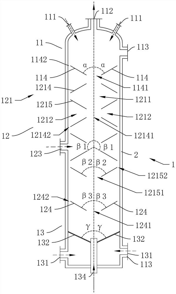
[0042] The embodiment of the present application discloses a multi-stage serial turbulent bed pyrolysis stripping reactor directly fed by a heat carrier. refer to figure 1 , the heat carrier directly feeds the heat type multi-stage series turbulent bed pyrolysis stripping reactor, including a shell 1, a refractory and heat-insulating lining 2 between the inner wall and the outer wall of the shell 1, and the shell 1 is distributed from top to bottom There are three areas, the upper reaction section 11, the middle reaction section 12 and the lower reaction section 13, which communicate with each other.

[0043] The high-temperature heat carrier rises from the lower reaction stage 13 to the upper reaction stage 11; the organic solid waste descends from the upper reaction stage 11 to the lower reaction stage 13; in the middle reaction stage 12, the descending organic solid waste directly contacts with the ascending high-temperature heat carrier to exchange heat, and the organic so...

Embodiment 2

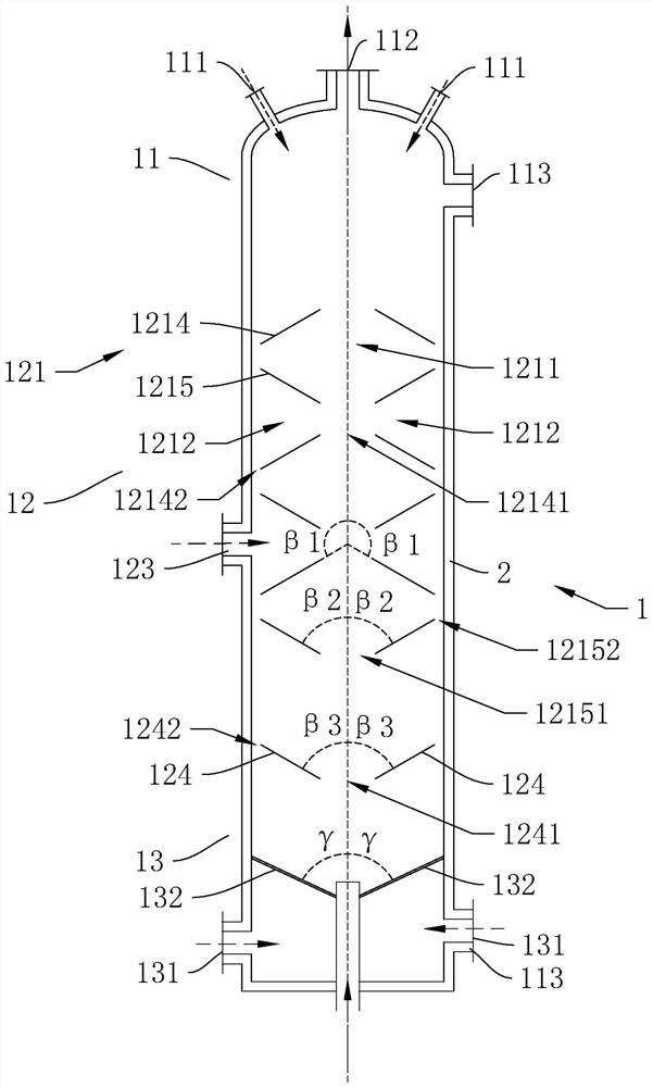
[0069] The difference between this embodiment and Embodiment 1 is that there is no material distribution plate 114 in the upper reaction section 11 , and the organic solid waste directly falls into the uppermost upper deflector 1214 in the reaction middle section 12 .

Embodiment 3

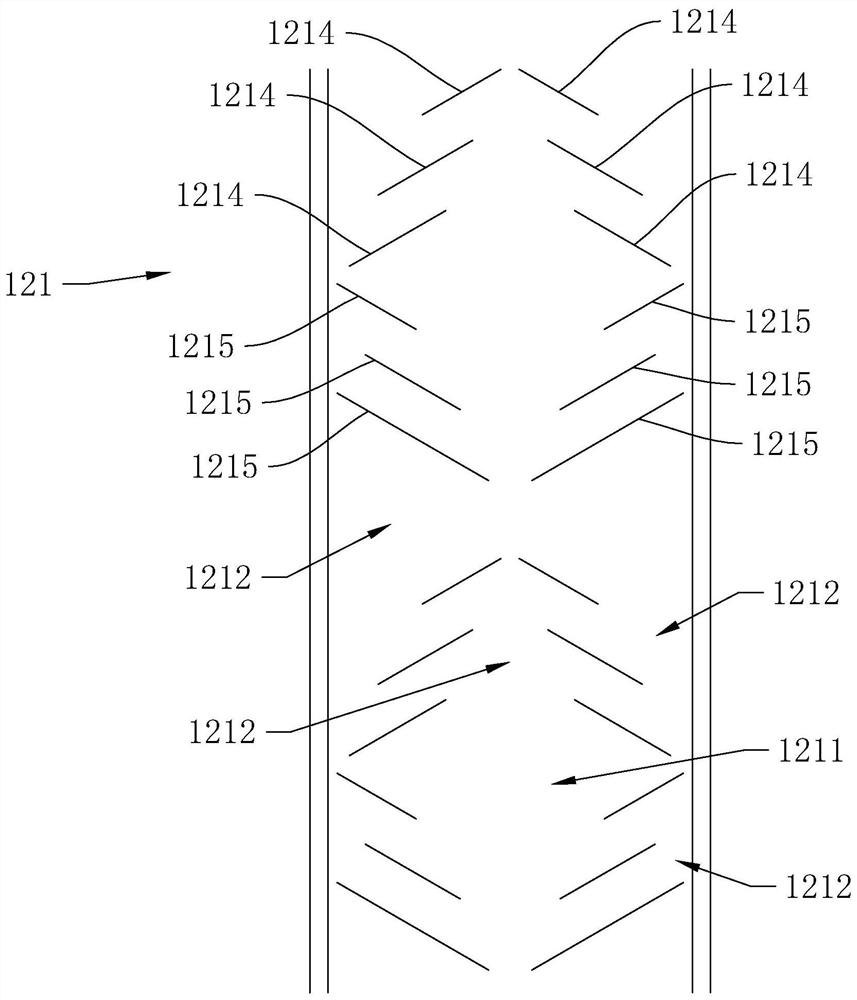
[0071] refer to image 3 , The difference between this embodiment and Embodiment 1 is that the structure of the turbulent micro-reaction bed 121 is different. Each group of turbulent micro-reaction beds 121 is composed of 3 upper deflectors 1214 and 3 lower deflectors 1215, and are bidirectionally symmetrical with the central axis of the shell 1 as the central axis and arranged in a ladder shape; the 3 upper deflectors The flow plates 1214 may be arranged at unequal intervals or at equal intervals.

[0072] The central area between the first upper deflector 1214 and the first lower deflector 1215 of each group constitutes the main reaction zone 1211 of this group of turbulent micro-reaction beds 121; 3 upper deflectors 1214 and shell Three secondary reaction zones 1212 are formed in the annular gap area between the inner walls of the body 1; three secondary reaction zones 1212 are formed in the central areas of the three upper deflectors 1214; the second and third lower defle...


PUM


Abstract

The invention relates to the field of solid waste treatment, in particular to a heat carrier direct heat supply type multi-stage series turbulent bed pyrolysis stripping reactor which comprises a shell, and the shell comprises an upper reaction section, a middle reaction section and a lower reaction section which communicate with one another; and the upper reaction section is provided with a solid waste inlet and a product outlet, the middle reaction section is provided with a plurality of groups of turbulent micro reaction beds which are connected in series, and the lower reaction section is provided with a heat carrier inlet and a residue outlet. The effect of improving the pyrolysis efficiency of the reactor is improved.

Description

technical field [0001] The present application relates to the field of solid waste treatment, in particular to a multi-stage serial turbulent bed pyrolysis stripping reactor with heat carrier direct heating. Background technique [0002] With the acceleration of my country's economic development and urbanization, the consumption of resources is increasing, the output of various wastes is increasing, the forms of waste are diversified, and problems such as soil and groundwater pollution are becoming more and more serious. National environmental protection regulations stipulate that solid wastes containing organic matter (i.e. organic solid wastes, most of which are hazardous wastes) need to be reduced and treated in a harmless manner to meet environmental protection emission requirements. Appropriate technology can be used to realize resource recovery Utilization, the polluted soil needs to be repaired and treated to meet the soil quality requirements for agricultural or urba...

Claims


Application Information

Patent Timeline
Patent Type & Authority Applications(China)
IPC IPC(8): C10B53/00
CPCC10B53/00
Inventor 郭文元郭强连卫平连海峰周鹤群蔡丽萍蔡文婷邵迪姜淑艳张丽银高凯陶成钢
Owner NINGBO LIANTONG EQUIP MFG
Why Eureka
Try Eureka