Mechanized oil pipe discharging machine used for oil field

It is a technology of pipe rowing machine and oil pipe, which is applied in the direction of drill pipe, casing pipe, drill pipe, etc. It can solve the problems of high labor intensity of workers and hidden dangers of manual operation safety, and achieve obvious use effect, reduce labor intensity and simple operation.

Inactive Publication Date: 2016-06-01
CHINA PETROLEUM & CHEM CORP +1
View PDF7 Cites 4 Cited by
  • Summary
  • Abstract
  • Description
  • Claims
  • Application Information

AI Technical Summary

Problems solved by technology

[0002] Oilfield tubing sending and receiving, repairing and inventory management are all provided by the second-level unit factories and stations. With the refinement of oilfield production and operation management, according to the requirements of standardized on-site placement, according to the "oil pipe layered discharge, ten out of ten According to the principle of placement, they are discharged on the pipe racks on the site respectively, and more than 12.5 million meters of oil pipe rods need to

Method used


Image

  • Mechanized oil pipe discharging machine used for oil field
  • Mechanized oil pipe discharging machine used for oil field
  • Mechanized oil pipe discharging machine used for oil field

Examples


Embodiment Construction

[0026] The detailed description and technical content of the present invention are described below with the accompanying drawings, but the accompanying drawings are only provided for reference and description, and are not intended to limit the present invention.

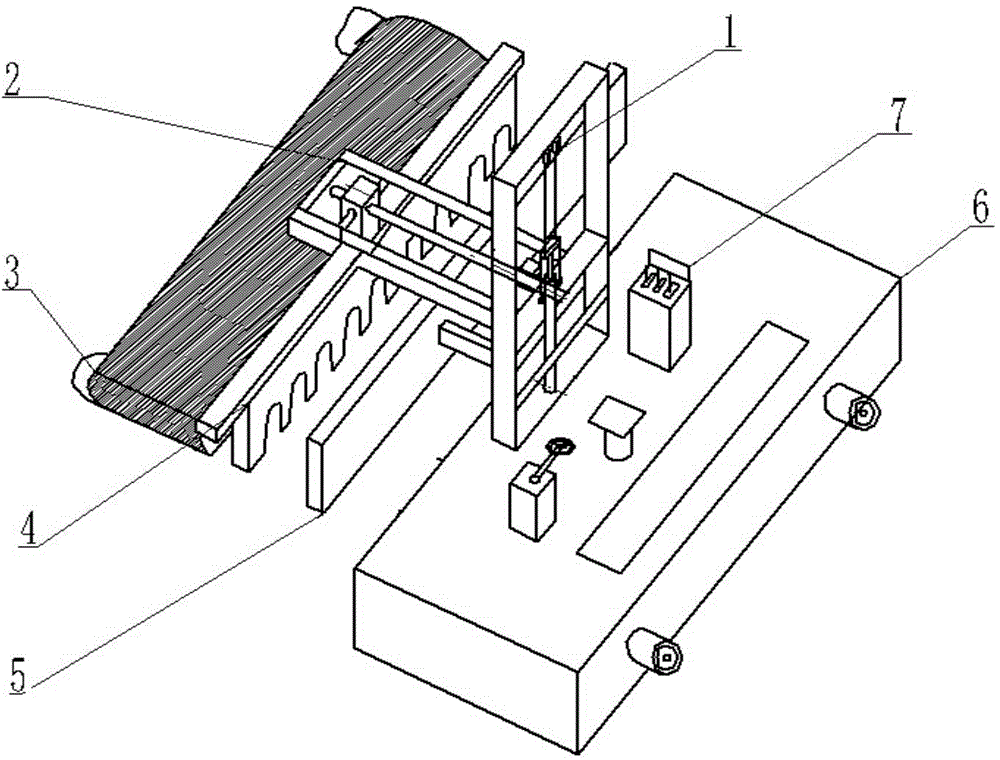
[0027] Refer to attached figure 1 , a mechanized tubing rowing machine for an oil field, comprising a tube lifting mechanism 1, a tube telescoping mechanism 2, a tube pulling mechanism 3, a tube scraper mechanism 4, a tube baffle mechanism 5, an electric traveling mechanism 6, Electric control operating mechanism 7. The pipe lifting mechanism 1 is welded on the frame of the pipe running mechanism 6, the pipe telescopic mechanism 2 is installed on the sliding lifting plate of the pipe lifting mechanism 1, and the pipe pulling mechanism 3 is connected to the pipe scraper mechanism 4 , The pipe scraper mechanism 4 is fixedly connected to the pulley of the pipe telescopic mechanism 2, below the telescopic roller assembl...


PUM


Abstract

The invention discloses a mechanized oil pipe discharging machine used for an oil field. The mechanized oil pipe discharging machine comprises a pipe discharging lifting mechanism, a pipe discharging telescopic mechanism, a pipe-discharging pipe-poking mechanism, a pipe discharging scraper blade mechanism, a pipe discharging baffle mechanism, an electric walking mechanism and an electrically controlled operation mechanism. A hydraulic cylinder is designed and installed on the pipe discharging lifting mechanism so as to achieve lifting of a pipe discharging mechanism, and the pipe discharging lifting mechanism is welded to a vehicle frame of the electric walking mechanism. A rolling wheel, a slideway, a turbine and a worm are designed for achieving stretching out and drawing back of the pipe discharging telescopic mechanism. The pipe discharging telescopic mechanism is installed on a sliding lifting plate of the pipe discharging lifting mechanism. A rolling belt-shaped structure is adopted for connecting the pipe-discharging pipe-poking mechanism to the pipe discharging scraper blade mechanism. Oil pipe segment hoop clamping grooves are designed for fixedly connecting the pipe discharging scraper blade mechanism to a pulley of the pipe discharging telescopic mechanism. The pipe discharging baffle mechanism is welded to a support cross brace of the pipe discharging lifting mechanism. The electrically controlled operation mechanism is installed on and connected to the electric walking mechanism. The electric walking mechanism, the vehicle frame and the pipe discharging mechanism are connected integrally. Mechanized oil pipe discharging is achieved, the pipe discharging work efficiency is improved, and the manual pipe discharging labor intensity of staff is relieved.

Description

technical field [0001] The invention relates to the storage and distribution management technology of oil pipes in oil fields, in particular to a mechanized oil pipe rowing machine for oil fields. Background technique [0002] Oilfield tubing sending and receiving, repairing and inventory management are all provided by the second-level unit factories and stations. With the refinement of oilfield production and operation management, according to the requirements of standardized on-site placement, according to the "oil pipe layered discharge, ten out of ten According to the placement principle, they are discharged on the pipe racks on the site respectively, and more than 12.5 million meters of oil pipe rods need to be placed every year; at present, the standardized discharge of oil pipes is completely manual operation, and each pipe rack is discharged by 4-5 people. The oil pipe is transported to the pipe rack by the pipe grasping machine, one person steps on the oil pipe and ...

Claims


Application Information

Patent Timeline
IPC IPC(8): E21B19/14
Inventor 郑雪梅程爱国綦耀升吴俊徐福刚何张华刘建生于宁
Owner CHINA PETROLEUM & CHEM CORP
Why Eureka
Try Eureka