Refrigeration system with filling level monitoring function

A refrigeration system, refrigerant technology, applied in the field of vehicle equipment, can solve problems such as expansion parts or refrigerant circuit blockage, compressor risk, wrong refrigerant state, etc.

Active Publication Date: 2016-06-01
KONVEKTA
View PDF12 Cites 14 Cited by
  • Summary
  • Abstract
  • Description
  • Claims
  • Application Information

AI Technical Summary

Problems solved by technology

[0009] Whereas the known methods from US5481884 and DE10061545A1 can indeed be applied in principle to any refrigerant and thus also to CO 2 , but the method only identifies the wrong refrigerant state at the compressor

Method used


Image

  • Refrigeration system with filling level monitoring function
  • Refrigeration system with filling level monitoring function
  • Refrigeration system with filling level monitoring function

Examples


Embodiment approach

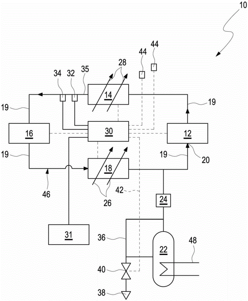
[0076] figure 1 is a schematic diagram of a refrigeration system 10 utilizing the refrigerant CO 2 run and can be used on the vehicle. CO 2 Also known as carbon dioxide and R-744. The refrigeration system 10 comprises a closed refrigerant circuit 46 with a compressor 12 , downstream of which a gas cooler 14 is arranged on the high-pressure side. The latter is followed by an expansion device 16 , through which the circulating refrigerant passing there is supplied in expanded and cooled form to an evaporator device 18 , which is connected on the suction side 20 to the compressor 12 . The various components 12 , 14 , 16 and 18 of the refrigeration system 10 are connected together by a pressure line 19 .

[0077] A storage vessel 22 , in which a certain amount of refrigerant is stored, is connected to the suction side 20 or to the corresponding pressure line 19 between the output side of the evaporator device 18 and the inlet or suction side 20 of the compressor 12 . The stor...


PUM


Abstract

The invention relates to a method and device used for monitoring refrigerant charge in a refrigerant loop (46) of a refrigeration system; the refrigeration system (10) comprises a compressor (12), a condenser or a gas cooler (14), an expansion device (16) and an evaporator device (18); when the compressor (12) is closed, the method comprises the following steps: measuring at least one temperature, and measuring refrigerant pressure in the refrigeration system; if the measured pressure is out of a nominal pressure scope, determining the refrigerant charge error, when the refrigerant is not enough, the refrigerant nominal pressure is determined according to the measured temperature, and the nominal pressure scope comprises the pressure value having the most regulated deviation from the nominal pressure; when the compressor is opened, the method comprises the following steps: measuring at least one temperature; measuring refrigerant pressure in the exit of the condenser or gas cooler; if the measured pressure is out of the nominal pressure scope, building the refrigerant charge error, especially the refrigerant is not enough, wherein the refrigerant nominal pressure is determined according to the measured temperature, and the nominal pressure scope comprises the pressure value and the pressure value having the most regulated deviation from the nominal pressure; the device also comprises a container (22) used for storing refrigerant; the refrigerant is specially CO2; the device runs in a cross critical range according to work points; at least one refrigerant temperature sensor (32) and at least one refrigerant pressure sensor (34) are provided so as to measure the temperature and pressure of the refrigerant; the refrigerant temperature and pressure can be evaluated in the mode in a control unit (30), so the refrigerant charge error can be detected if the insufficiency is detected, the control unit can control medium on the refrigerant loop (46) so as to start filling.

Description

technical field [0001] The invention relates to a method for monitoring the refrigerant charge of a refrigerant circuit of a refrigeration system to fill such a refrigeration system with refrigerant and to a device, in particular for a vehicle, for monitoring a refrigeration system refrigerant charge. Background technique [0002] Compression refrigeration systems or air-conditioning systems are used as air-conditioning systems, for example, in air-conditioned vehicles, such as cars or buses, in order to reduce the temperature inside the vehicle. A compression refrigeration system of the type described above comprises a refrigerant delivery system having a condenser unit comprising at least one condenser or at least one gas cooler, in addition to an expansion device, an evaporator unit and a compressor through which the refrigerant Conveyor lines are connected together. Refrigerant circulates in this closed circuit. [0003] According to environmental compatibility, carbo...

Claims


Application Information

Patent Timeline
IPC IPC(8): F25B45/00F25B49/00
CPCB60H1/3225B60H2001/325B60H2001/3257F25B9/008F25B45/00F25B49/005F25B2309/061F25B2345/001F25B2500/24F25B2700/04F25B2700/195F25B2700/21163
Inventor 米歇尔·宗内卡尔布哈特穆特·贡佩尔邦雅曼·黑尔维希塞巴斯蒂安·芬克菲利普·梅尔
Owner KONVEKTA
Why Eureka
Try Eureka