
Temperature compensation system and method of pressure sensor

A pressure sensor and temperature compensation technology, which is applied in the measurement of the property force of piezoelectric resistance materials, etc., which can solve the loss of measurement accuracy, the difficulty in solving the relationship between the output of a silicon piezoresistive pressure sensor and temperature, and the inability to complete temperature compensation, etc. problems, to achieve the effect of reducing production costs and improving measurement accuracy

Active Publication Date: 2016-06-01
WUHAN AVIATION SENSING TECH
View PDF8 Cites 15 Cited by
  • Summary
  • Abstract
  • Description
  • Claims
  • Application Information

AI Technical Summary

Problems solved by technology

The third is the combination of analog compensation and digital compensation. This method uses analog compensation to reduce the influence of temperature on the silicon piezoresistive pressure sensor, so as to reduce the measurement error caused by the measurement temperature, but it is essentially digital compensation, and the measurement accuracy is limited. The influence of selection and number of calibration temperature points
However, the wider the operating temperature range, the more difficult it is to solve the relationship between the output of the silicon piezoresistive pressure sensor and the temperature
The existing compensation method only increases the calibration temperature point in order to adapt to a wider working temperature range, but for the silicon piezoresistive pressure sensor with an integrated signal conditioning chip that can only have three calibration temperature points, the measurement accuracy will be lost, or even impossible. complete temperature compensation

Method used


Image

  • Temperature compensation system and method of pressure sensor
  • Temperature compensation system and method of pressure sensor
  • Temperature compensation system and method of pressure sensor

Examples


Embodiment Construction

[0074] The principles and features of the present invention are described below in conjunction with the accompanying drawings, and the examples given are only used to explain the present invention, and are not intended to limit the scope of the present invention.

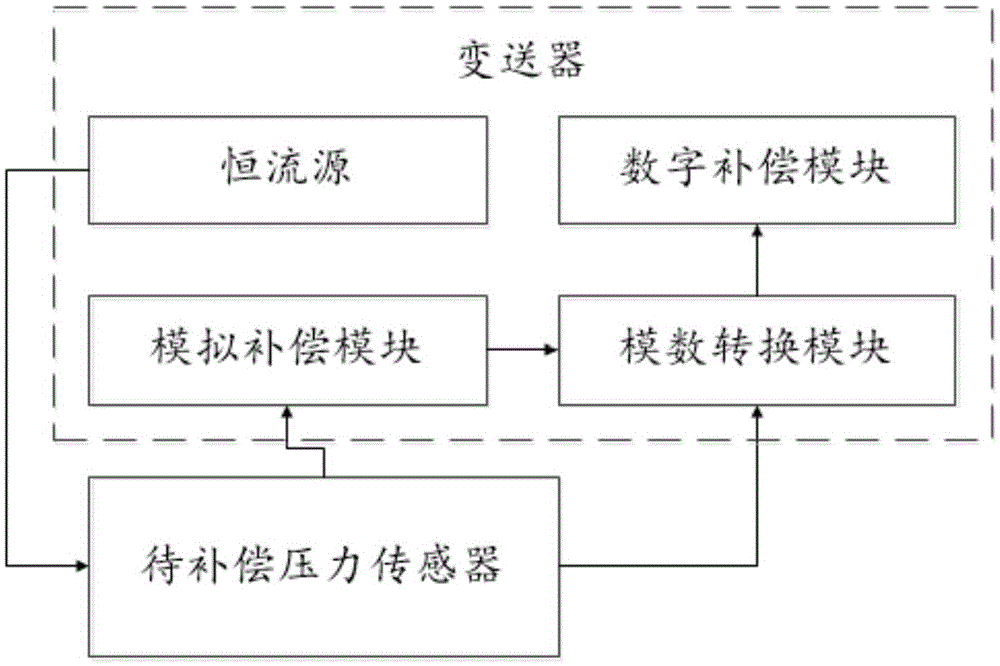
[0075] Such as figure 1 As shown, a temperature compensation system for a pressure sensor includes a pressure sensor to be compensated and a transmitter;

[0076] The pressure sensor to be compensated is a silicon piezoresistive pressure sensor driven by a constant current source;

[0077] The transmitter includes a constant current source, an analog compensation module, an analog-to-digital conversion module and a digital compensation module;

[0078] The constant current source is used to provide the driving power of the pressure sensor to be compensated;

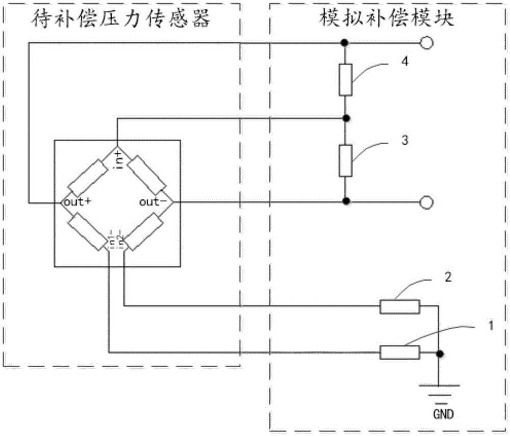
[0079] The analog compensation module is used to convert the output voltage of the pressure sensor to be compensated, so that the relationship between the co...


PUM


Abstract

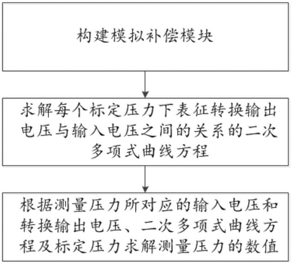
The invention relates to a temperature compensation system and method of a pressure sensor. By taking input voltages of a pressure sensor to be compensated as temperature signals, an analog compensation module converts output voltages of the pressure sensor to be compensated to enable the relation between the converted output voltages and the input voltages of the pressure sensor to be compensated to be fitted by a quadratic polynomial curve under the condition of certain pressure so that a quadratic polynomial curve equation representing the relation between the converted output voltages and the input voltages under each calibration pressure can be determined only through three calibration temperature points in a digital compensation module, a value of measurement pressure is solved accordingly, and thus a whole temperature compensation process is completed. Through combining analog compensation with digital compensation, high-precision measurement of a constant-current source driving type silicon piezoresistive pressure sensor is realized only through the three calibration temperature points.

Description

technical field [0001] The invention relates to the field of pressure signal measurement, in particular to a temperature compensation system and method for a pressure sensor. Background technique [0002] The phenomenon of output drifting with temperature is an inherent characteristic of silicon piezoresistive pressure sensors, and it is necessary to take temperature compensation measures to correct its output to eliminate the influence of temperature. At present, there are three methods of temperature compensation: one is analog compensation, in which passive devices such as resistors and thermal elements are connected in series and in parallel at the input and output ends of the silicon piezoresistive pressure sensor, and the temperature of the silicon piezoresistive pressure sensor is reduced by shunting or dividing pressure. The output is affected by temperature; this method has a simple circuit, but it is difficult to debug and the compensation accuracy is not high. Th...

Claims


Application Information

Patent Timeline
IPC IPC(8): G01L1/18
CPCG01L1/18
Inventor 王博欧阳敏龚珊
Owner WUHAN AVIATION SENSING TECH
Learn More