Device and method for measuring conductor current through employing magneto-optic materials

A magneto-optical material, conductor current technology, applied in measuring devices, measuring current/voltage, measuring only current, etc., can solve the problems of measurement errors, hidden dangers of public safety and normal life order, and high energy consumption

Active Publication Date: 2016-06-01
HEBEI UNIVERSITY +1
View PDF4 Cites 7 Cited by
  • Summary
  • Abstract
  • Description
  • Claims
  • Application Information

AI Technical Summary

Problems solved by technology

At present, the electromagnetic mutual inductance measurement method is generally used in this field. The measurement technology of this method is very mature, but there are some serious shortcomings: 1. The equipment is bulky (because there are wire packages and iron cores); 2. During the mutual inductance process High energy consumption; 3. In order to prevent overheatin

Method used


Image

  • Device and method for measuring conductor current through employing magneto-optic materials
  • Device and method for measuring conductor current through employing magneto-optic materials
  • Device and method for measuring conductor current through employing magneto-optic materials

Examples


Embodiment 1

[0094] Embodiment 1, a method for measuring conductor current by using a magneto-optical material.

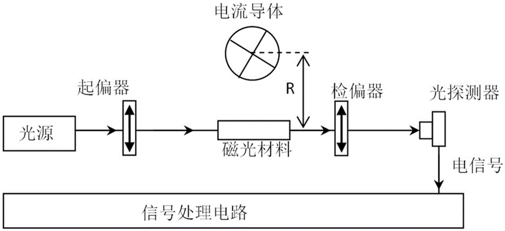
[0095] The embodiment of the present invention uses two magneto-optical crystals (a kind of magneto-optical material) as the sensing head (or current sensing device), measures the conductor current and eliminates the measurement error caused by the distance error between the sensing head and the conductor, The specific theoretical basis is as follows:

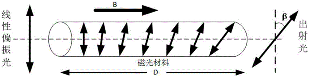
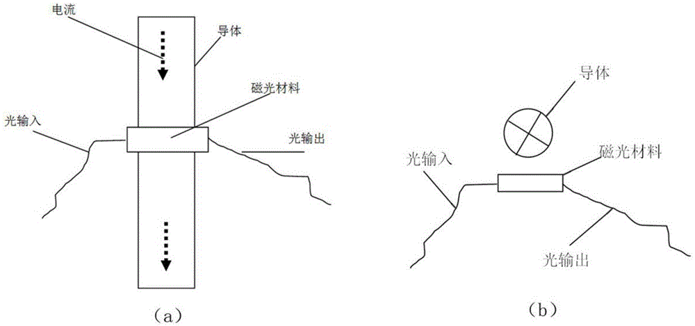
[0096] Such as figure 1 and image 3 As shown, when the current in the conductor is I, the magnetic induction intensity at the position of the magneto-optical material whose distance from the conductor is R is B. According to the Ampere loop theorem, the relationship between B and I is:

[0097]

[0098] Suppose the conductor is a long straight wire, when the current is I, the magnetic induction intensity B at the distance R from the conductor is:

[0099] B = μ ...

Embodiment 2

[0132] Embodiment 2, a device for measuring conductor current using a magneto-optical material.

[0133] Such as Figure 5 As shown, the device in this embodiment includes a first magneto-optic crystal 1, a second magneto-optic crystal 2, a beam splitter 4, a first polarizer 5, a second polarizer 6, a first analyzer 7, a first polarizer Two analyzers 8, a first photodetector 9, a second photodetector 10, a signal processing circuit, a light source, and an optical path transmission device (such as an optical fiber, etc.) to realize the connection of these devices.

[0134] The first magneto-optic crystal 1 and the second magneto-optic crystal 2 are all arranged in the vicinity of the conductor 3 to be measured (cross section shown in the figure), and the first magneto-optic crystal 1 and the second magneto-optic crystal 2 are apart from the conductor 3 to be measured The installation distance is not limited, but the relative position of the two magneto-optic crystals must be k...

Embodiment 3

[0141] Embodiment 3, a device for measuring conductor current using a magneto-optical material.

[0142] Such as Figure 6 As shown, the difference between this embodiment and Embodiment 2 is that the polarization beam splitting unit in this embodiment is composed of a first polarizer 5 and a beam splitter 4 . The first polarizer 5 is placed behind the light source, which is used to receive the measurement light emitted by the light source and generate a beam of linearly polarized light. The beam splitter 4 is arranged between the first polarizer 5 and the two magneto-optical crystals, and the beam splitter 4 is used to split a beam of linearly polarized light from the first polarizer 5 into two beams of linearly polarized light, respectively Transmitting linearly polarized light (that is, the first linearly polarized light) and reflecting linearly polarized light (that is, the second linearly polarized light); the two beam-split linearly polarized lights are respectively inc...


PUM


Abstract

The invention provides a device and method for measuring a conductor current through employing magneto-optic materials. The two magneto-optic materials are arranged to be opposite to each other, and serve as current sensing devices at the same time. The device and method guarantee that the relative position of the two magneto-optic materials is not changed in a measurement process of the conductor current. When the two magneto-optic materials are located in a magnetic field formed by an electrified conductor, the polarization directions of polarized light passing through the magneto-optic materials will be changed because of the Faraday effect. Through the measurement of the deflection angles of two polarized light beams after the polarized light beams pass through the two magneto-optic materials, the device and method can calculate the current in a conductor through the difference between the distances from optical paths in the two magneto-optic materials to the center of the conductor. When the device and method are used for measuring the conductor current, the installation distances of the two magneto-optic materials to the conductor are not sensitive, and a measurement error caused by the nondeterminacy of the position between the magneto-optic materials and the conductor in the prior art can be eliminated.

Description

technical field [0001] The invention relates to the technical field of current measurement, in particular to a device and method for measuring conductor current by using magneto-optical materials. Background technique [0002] Current measurement, especially large current measurement, is an important task in power system, power supply system and large-scale production enterprises in terms of power guarantee. At present, the electromagnetic mutual inductance measurement method is generally used in this field. The measurement technology of this method is very mature, but there are some serious shortcomings: 1. The equipment is bulky (because there are wire packages and iron cores); 2. During the mutual inductance process High energy consumption; 3. In order to prevent overheating, it is necessary to immerse the heating part of the equipment in oil, which brings great hidden dangers to public safety and normal life order. [0003] In recent years, the use of optical sensing te...

Claims


Application Information

Patent Timeline
IPC IPC(8): G01R19/00
CPCG01R19/0092
Inventor 尉长江姚晓天钦明亮
Owner HEBEI UNIVERSITY
Why Eureka
Try Eureka