Power load test system

A technology of power load and test system, applied in signal transmission system, electric power measurement through current/voltage, measurement of electricity, etc., can solve problems such as timely maintenance of unfavorable equipment and poor real-time effect.

Inactive Publication Date: 2016-06-01
STATE GRID CORP OF CHINA +1
View PDF0 Cites 1 Cited by
  • Summary
  • Abstract
  • Description
  • Claims
  • Application Information

AI Technical Summary

Problems solved by technology

At present, the real-time effect of the power load test is not good, which is not conducive to the timely maintenance of equipment

Method used

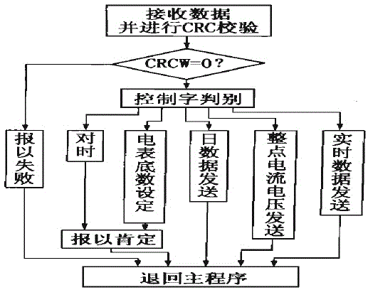

Image

  • Power load test system

Examples


Embodiment Construction

[0012] As shown in the figure, the present invention includes a power load parameter tester for monitoring transformer operating parameters and a main station management system installed in the management department for real-time data display and printing reports; the main station hardware consists of a computer, a modem, a wireless station , an omnidirectional antenna and a printer.

[0013] The main control CPU in the tester of the present invention adopts a single-chip microcomputer 80C196KC.

[0014] The current and voltage signals of the three-phase transformer of the present invention are obtained through current transformers and voltage transformers, and the current and voltage signals of one of the phases are selected by an analog electronic switch to be sent to a sampling and holding circuit mainly composed of LF398, and the signal is sampled and held by two 80C196KC The A / D conversion interface of each route is sampled separately to obtain the current and voltage val...


PUM


Abstract

The present invention provides a power load test system, belonging to the field of the test system technology, and especially relate to a power load test system. The present invention provides a power load test system with a test real-time effect and an accurate test. The power load test system comprises a power load parameter tester configured to monitor operation parameters of a transformer and a master station management system installed at a management department and configured to display real-time data and print reports, wherein master station hardware consists of a computer, a modem, a radio station, an omnidirectional antenna and a printer.

Description

technical field [0001] The invention belongs to the technical field of test systems, in particular to an electric load test system. Background technique [0002] The total load of the power system is the sum of the total power consumed by all electrical equipment in the system; adding the power consumed by industry, agriculture, post and telecommunications, transportation, municipal, commercial, and urban and rural residents gives the comprehensive power load of the power system; The power of the comprehensive power load plus network loss is the power that each power plant in the system should supply, which is called the power supply load (power supply) of the power system; the power supply load is added to the power consumed by each power plant itself (that is, the factory power), It is the power that each generator in the system should generate, which is called the power generation load of the system. At present, the real-time effect of the power load test is not good, wh...

Claims


Application Information

Patent Timeline
Patent Type & Authority Applications(China)
IPC IPC(8): G01R21/06G01R31/00G08C17/02
Inventor 李大军陈洪坤
Owner STATE GRID CORP OF CHINA
Why Eureka
Try Eureka