
A New Fresnel Optical Antenna Launching System

A technology of optical antenna and transmitting system, applied in the field of optical communication, can solve the problem of energy loss in the center of the secondary mirror of the antenna

Inactive Publication Date: 2017-12-05
UNIV OF ELECTRONICS SCI & TECH OF CHINA
View PDF5 Cites 0 Cited by
  • Summary
  • Abstract
  • Description
  • Claims
  • Application Information

AI Technical Summary

Problems solved by technology

[0007] The present invention aims at the deficiencies existing in the existing optical antenna, solves the key technical problem of energy loss in the center of the secondary mirror of the antenna, and provides a new Fresnel optical antenna transmitting system structure

Method used


Image

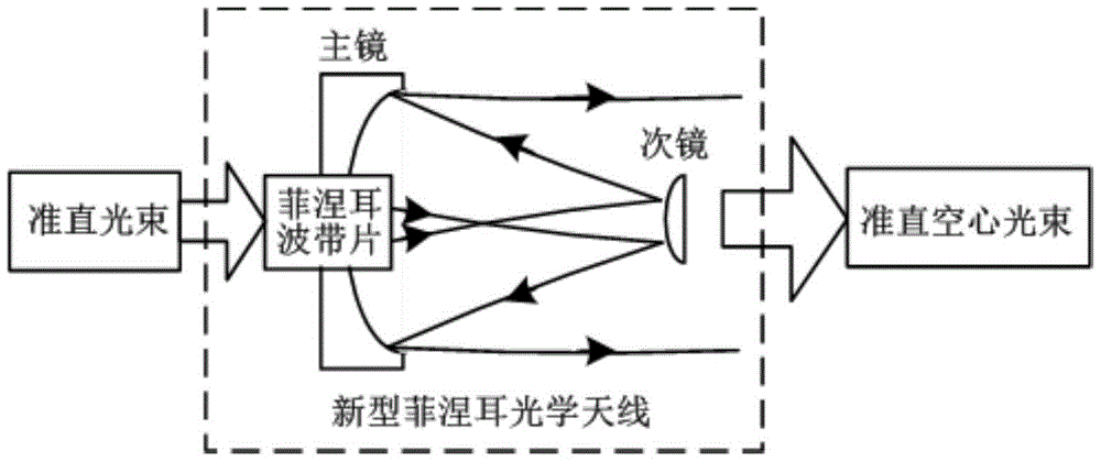
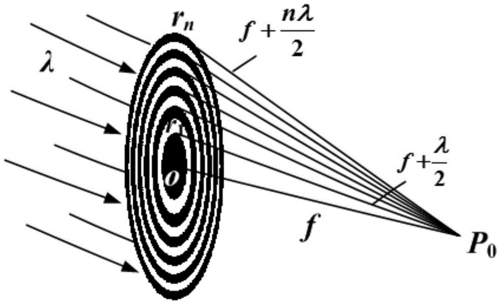
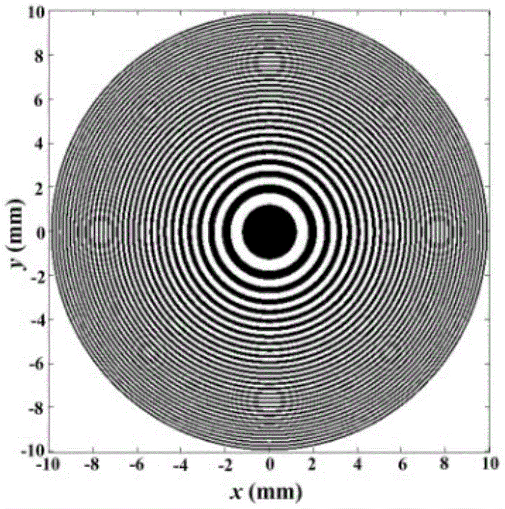
  • A New Fresnel Optical Antenna Launching System
  • A New Fresnel Optical Antenna Launching System
  • A New Fresnel Optical Antenna Launching System

Examples


Embodiment Construction

[0019] The present invention will be further elaborated and illustrated below in conjunction with the accompanying drawings and embodiments.

[0020] figure 1 As shown, it is a structural block diagram of a Fresnel optical antenna transmitting system of the present invention, and the system is composed of an amplitude-type Fresnel zone plate and a Cassegrain optical antenna. The circular Fresnel zone plate is fixed in the central hole of the primary mirror of the antenna. The collimated plane light wave is incident on the Fresnel zone plate and then focused. The main focus coincides with the left focus of the secondary mirror, and a The dark hollow beam is transmitted by the optical antenna to form a collimated hollow beam.

[0021] figure 2 As shown, the schematic diagram of a plane wave illuminating a circular Fresnel optical zone plate. The zone plate is a special grating composed of a group of light-transmitting and opaque concentric rings alternately spaced, and the c...


PUM


Abstract

The invention belongs to the technical field of optical communication, in particular to a novel Fresnel optical antenna transmitting system. The Fresnel optical antenna transmitting system consists of an amplitude Fresnel zone plate and a Cassegrain optical antenna. The Fresnel zone plate adopted in the present invention is composed of light-transmitting and opaque wave-zones alternately, located in the central circular hole of the parabolic primary mirror of the antenna, focusing the incident plane wave, the main focus and the secondary mirror of the rotating hyperboloid The left focus coincides, and the center of the light spot generated at the secondary mirror is a dark spot, which can effectively avoid the large central energy loss in the process of reflecting the light through the secondary mirror of the antenna to the primary mirror. After the beam is reflected by the secondary mirror and the primary mirror successively, a collimated hollow beam is generated and transmitted in free space. The invention mainly solves the key technical problem of energy loss in the center of the secondary mirror in the traditional optical antenna, helps to improve the transmission efficiency and emission accuracy of the transmitting antenna in the optical communication system, and is easy to realize the miniaturization of the optical communication transmitting system.

Description

technical field [0001] The invention belongs to the technical field of optical communication, in particular to a novel Fresnel optical antenna transmitting system. Background technique [0002] The main function of the optical antenna system is to expand the laser beam and further compress the divergence angle. Optical antennas are key transmitting and receiving subsystems in the field of optical communication technology. High-precision collimation technology and high transmission efficiency are important guarantees for optical antenna systems to achieve long-distance transmission and high tracking accuracy. [0003] Space optical communication usually involves multi-wavelength transmission, and a reflective system without chromatic aberration (Cassegrain type telescope) is widely used as the transmitting and receiving antenna, because a large amount of energy of the laser Gaussian beam is collected in the center (light) during the axial transmission process. On the axis, t...

Claims


Application Information

Patent Timeline
Patent Type & Authority Patents(China)
IPC IPC(8): G02B17/08G02B27/00H01Q19/10
CPCG02B17/0804G02B27/0012H01Q19/10
Inventor 江萍杨华军李军
Owner UNIV OF ELECTRONICS SCI & TECH OF CHINA
Learn More