Visual optical imaging device and binocular near-eye display using same

An optical imaging and optical surface technology, which is applied in the field of ultra-thin visual display technology, can solve the problems of small viewing angle, splitting, and increase the burden on the user's head, and achieves improved wearing comfort, light and thin optical structure, and viewing angle. big effect

Active Publication Date: 2019-06-14
BEIJING NEDPLUSAR DISPLAY TECH CO LTD
View PDF6 Cites 1 Cited by
  • Summary
  • Abstract
  • Description
  • Claims
  • Application Information

AI Technical Summary

Problems solved by technology

Among the above-mentioned products, except for Microsoft’s Hololens, most of them adopt non-optical transmissive solutions, that is, users are separated from the real world when using them, or they can only target the user’s single eye, resulting in a small viewing angle and affecting User's Visual Experience
At the same time, in order to pursue the sense of immersion, the optical components of most existing VR products located in front of the user's eyes have a relatively large thickness and are closed around the eyes. When wearing it, a counterweight system is even required to balance the weight, which increases the burden on the user's head. , it is impossible to realize a thin and light optical transmissive binocular near-eye display
[0003] In order to realize the ultra-thin optical transmissive near-eye display solution, some designs introduce free-form prism elements, and realize optical transmission by means of catadioptric and compensating prisms. In some cases, the thickness of the optical system of this scheme cannot be very thin, which limits the further thinning of the binocular near-eye display; while other designs use the planar light waveguide scheme, using the light inside the planar waveguide element. Reflection effectively reduces the thickness of the optical element, but the planar waveguide element cannot provide optical power and needs to be used with a complex projection system

Method used


Image

  • Visual optical imaging device and binocular near-eye display using same
  • Visual optical imaging device and binocular near-eye display using same
  • Visual optical imaging device and binocular near-eye display using same

Examples


no. 1 example

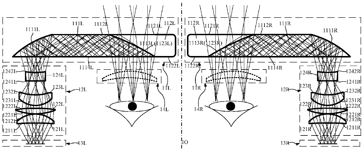
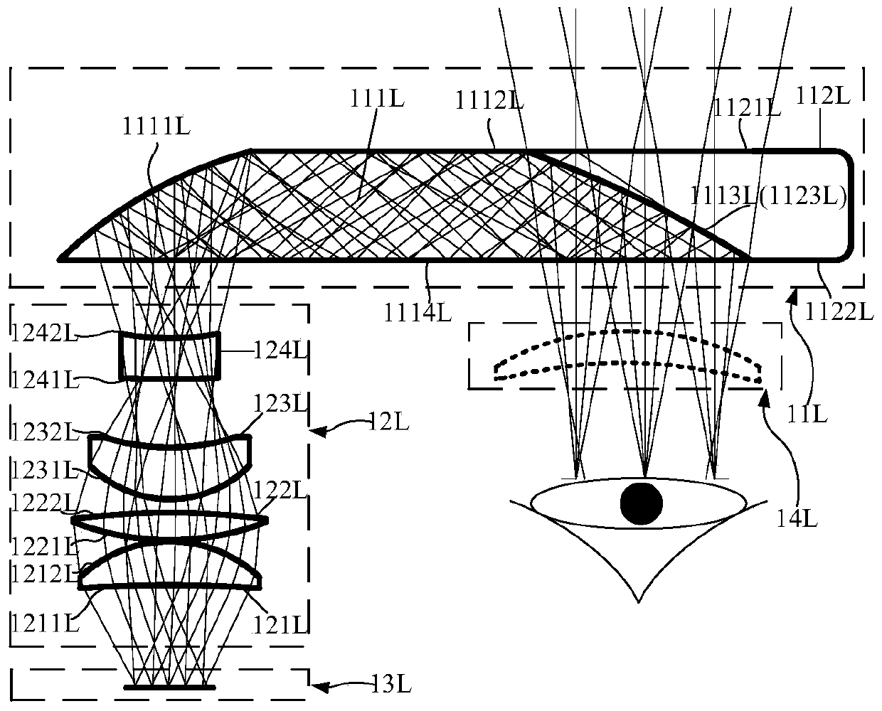
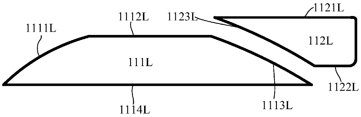
[0022] Such as Figure 1-3 As shown, the visual optical imaging device for binocular near-eye display according to the first embodiment of the present invention includes two left and right visual optical imaging devices, figure 1 The optical path diagram of the binocular near-eye display of the first embodiment of the present invention is shown in , which is embodied in the cross-sectional view of the near-eye display. Since the two sets of visual optical imaging devices are symmetrically distributed about the central axis 10, hereinafter, the Taking the visual optical imaging device on the left side as the specific description object to illustrate the specific embodiment of the present invention, those skilled in the art can understand that the visual optical imaging device on the right side has the same structure as the left side, but the left and right are reversed.

[0023] Such as figure 2 As mentioned above, the left-side visual optical imaging device of the first embo...

no. 2 example

[0044] Similar to the first embodiment, the second embodiment of the present invention is as Figure 4 As shown, there are also two sets of visual optical imaging devices that are left and right symmetrical, and the left side is still used as an example for illustration below. The left visual optical imaging device according to the second embodiment of the present invention includes a free-form surface waveguide element 21L and a projection optical assembly 22L, and a micro display element 23L is placed on the object side of the projection optical assembly 22L. The image light signal emitted by the micro-display element 23L passes through the lenses 221L, 222L, 223L, and 224L of the projection optical assembly 22L in sequence, then enters the interior of the waveguide element through the surface 2114L of the free-form surface waveguide element 21L, and is incident on the surface 2111L for reflection. After being reflected by 2111L, the light satisfies the total internal reflec...

no. 3 example

[0055] Similar to the first and second embodiments, the third embodiment of the present invention is as Figure 5 As shown, taking the left side as an example, it includes a free-form surface waveguide element 31L and a projection optical assembly 32L, and the microdisplay element 33L is placed on the object side of the projection optical assembly 32L. The image light signal emitted by the micro-display element 33L passes through the lenses 321L, 322L, 323L, and 324L of the projection optical assembly 32L in sequence, then enters the interior of the waveguide element through the surface 3114L of the free-form surface waveguide element 31L, and is incident on the surface 3111L for reflection. After being reflected by 3111L, the total internal reflection condition of light is satisfied, and the transmission is completed by total reflection between the surface 3114L and the surface 3112L, until the light incident on the surface 3113L is reflected and no longer satisfies the total ...


PUM


Abstract

The present invention relates to a visual optical imaging device and an ultrathin optics transmission-type near-eye display by using the same. The near-eye display is formed by bilaterally symmetrically arranging two same visual optical imaging devices, each visual optical imaging device including one free-form surface waveguide component and one projection optics assembly; and the projection optics assemblies are used for projecting image signals emitted by an image source component to the light incident plane of the free-form surface waveguide component, the light ray is propagated in the free-form surface waveguide component to an exit pupil direction by means of a total reflection condition and enters users' glasses after being emitted from the exit surface when the total internal reflection condition is satisfied, and the light rat in the transmission direction is able to normally transmit to enter users' eyes, so that the ultrathin near-eye display is realized.

Description

technical field [0001] The invention relates to a visual optical imaging device and an ultra-thin optical transmissive near-eye display using the same, in particular to an ultra-thin visual display technology combining a free-form surface and a waveguide element. Background technique [0002] Consumer electronics products have developed vigorously in recent years. After smart phones, consumers have generally known the concepts of virtual reality (virtual reality) and augmented reality (augmented reality), and are chasing related concept products as a new experience technology. try. In the field of VR, companies such as Samsung, Sony, Oculus, and HTC have produced products that provide consumers with VR display devices that can be used independently with the help of smartphones; while in the field of AR, the products of companies such as Google and Microsoft are also Staying at the stage of conceptual product development and display, the number of commercially available prod...

Claims


Application Information

Patent Timeline
Patent Type & Authority Patents(China)
IPC IPC(8): G02B27/01
CPCG02B27/0101G02B27/0172G02B2027/0132G02B2027/0134G02B2027/0178
Inventor 程德文王其为
Owner BEIJING NEDPLUSAR DISPLAY TECH CO LTD
Why Eureka
Try Eureka