Manufacturing method for signal line of display panel

A manufacturing method and display panel technology, applied in nonlinear optics, instruments, optics, etc., can solve the problems of large improvement costs, increased mask manufacturing costs, and limited reduction in line spacing.

Inactive Publication Date: 2016-06-01
SHENZHEN CHINA STAR OPTOELECTRONICS TECH CO LTD
View PDF5 Cites 5 Cited by
  • Summary
  • Abstract
  • Description
  • Claims
  • Application Information

AI Technical Summary

Problems solved by technology

However, the former requires a lot of improvement costs, while the latter will incr

Method used


Image

  • Manufacturing method for signal line of display panel
  • Manufacturing method for signal line of display panel
  • Manufacturing method for signal line of display panel

Examples


Embodiment Construction

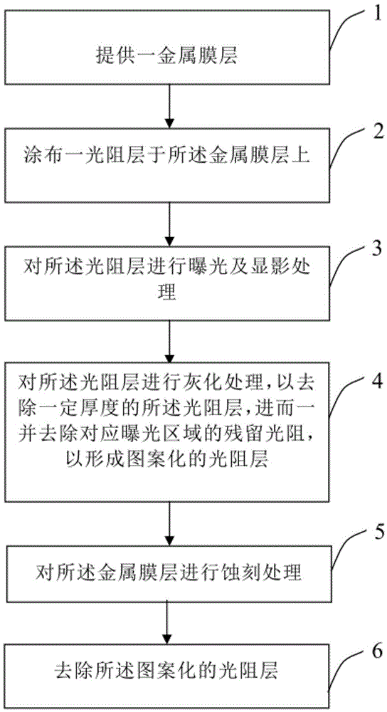
[0025] In order to make the above objectives, features and advantages of the present invention more comprehensible, the preferred embodiments of the present invention will be described in detail below in conjunction with the accompanying drawings. Furthermore, the directional terms mentioned in the present invention, such as "up", "down", "front", "back", "left", "right", "in", "out", "side", etc., Only refer to the direction of the attached drawings. Therefore, the directional terms used are used to describe and understand the present invention, rather than to limit the present invention.

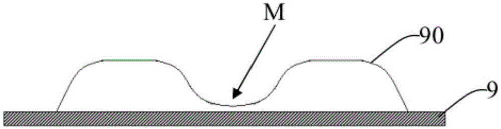
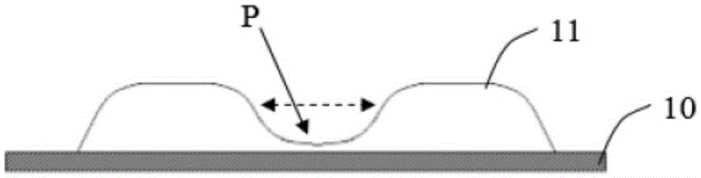
[0026] The signal line manufacturing method of the present invention is suitable for the signal line manufacturing process of general display panels (such as thin film transistor liquid crystal displays). The signal lines can be scan lines, data lines, or other traces made of metal, for example, of thin film transistor liquid crystal displays. line. The signal line can be a single metal lay...


PUM


Abstract

The invention discloses a manufacturing method for a signal line of a display panel.The manufacturing method for the signal line of the display panel comprises the steps that firstly, a metal membrane layer is coated with light resistance; after exposure and development are carried out, the light resistance layer is further removed by a certain thickness through ashing treatment, and residual light resistance in a corresponding exposure region is further removed to form a patterned light resistance layer; then the metal membrane layer is etched to form the signal line.

Description

【Technical Field】 [0001] The present invention relates to the field of flat display, in particular to a method for manufacturing signal lines of a display panel. 【Background technique】 [0002] In the thin-film transistor liquid crystal display (Thin-Film Transistor Liquid Crystal Display, TFT-LCD) manufacturing process, the line pitch is a very important parameter, which directly affects many TFT-LCD characteristics, such as the minimum channel length directly affects the thin film transistor Driving capability; the minimum distance between the scan line and the signal line will affect the wiring design of the fan-out area, and then affect the characteristics of the liquid crystal panel such as the frame width and signal delay of the thin film transistor liquid crystal display. [0003] With the development of liquid crystal panels in the direction of refinement and high quality, the line spacing is also required to be smaller and smaller. Generally, the minimum line spacing in t...

Claims


Application Information

Patent Timeline
IPC IPC(8): G02F1/1362
CPCG02F1/136286G02F1/136295
Inventor 姜祥卫
Owner SHENZHEN CHINA STAR OPTOELECTRONICS TECH CO LTD
Why Eureka
Try Eureka