Finite element model optimization device and method

An optimization method, finite element technology, applied in special data processing applications, instruments, electrical digital data processing, etc., can solve problems such as finite element modeling distortion, and achieve the effect of reliable analysis model

Inactive Publication Date: 2016-06-01
BEIJING AERONAUTIC SCI & TECH RES INST OF COMAC +1
View PDF0 Cites 22 Cited by
  • Summary
  • Abstract
  • Description
  • Claims
  • Application Information

AI Technical Summary

Problems solved by technology

[0005] Embodiments of the present invention provide a finite element model optimization method and device to

Method used


Image

  • Finite element model optimization device and method
  • Finite element model optimization device and method
  • Finite element model optimization device and method

Examples


Embodiment 1

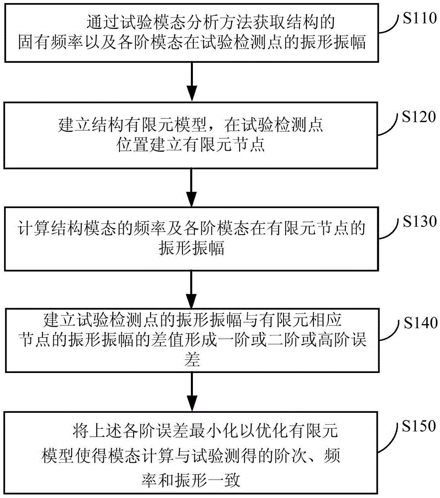
[0031] figure 1 A finite element model optimization method provided in Embodiment 1 of the present invention can be executed by a finite element model optimization device, wherein the optimization device can be realized by software and / or hardware, and can generally be integrated in a computer.

[0032] see figure 1 , the finite element model optimization method of this embodiment includes the following steps: Step S110, obtain a set of natural frequencies of the structure and vibration amplitudes of the corresponding modes at test detection points through the test modal analysis method.

[0033] Specifically, during the test modal analysis process, the excitation method is used to collect the modal parameters. The modal parameters include: the natural frequency of the structure, the vibration amplitude of each mode at the test detection point, the modal mass, and the modal Vectors, modal stiffness and modal damping, etc. In this embodiment, the test modal analysis method re...

Embodiment 2

[0081] Figure 6 It is a schematic structural diagram of a finite element model optimization device provided in Embodiment 2 of the present invention. The optimization device is configured in a computer. The optimization device in this embodiment specifically includes: a test mode parameter acquisition module 61 , a finite element model processing module 62 , an error establishment module 63 , and an optimization module 64 .

[0082] Wherein, the test modal parameter acquisition module 61 is used to acquire a set of natural frequencies of the structure and vibration shape amplitudes of corresponding modes at the test detection points through the test modal analysis method.

[0083] Specifically, during the test modal analysis process, the excitation method is used to collect the modal parameters. The modal parameters include: the natural frequency of the structure, the vibration amplitude of each mode at the test detection point, the modal quality, and the modal Vectors, mod...


PUM


Abstract

The embodiment of the invention discloses a finite element model optimization device and method. The method comprises the following steps: through an experimental modal analysis method, obtaining the inherent frequency of a structure and the vibration form amplitude of each-order modal on an experiment detection point; establishing a structure finite element model, and establishing a corresponding finite element node on the position of the experimental detection point; calculating the frequency of a structural modal and the vibration form amplitude of each-order model on the finite element node; establishing a difference value of the vibration form amplitude of the experiment detection point and the vibration form amplitude of the corresponding finite element node to form first-order, second-order or high-order errors; and taking the minimization of the each-order error as an optimization objective to optimize the finite element model. The problem that finite element modeling is distorted in traditional structural modal calculation analysis is solved.

Description

technical field [0001] The embodiments of the present invention relate to the field of mechanical structure design, in particular to a finite element model optimization device and method. Background technique [0002] Generally speaking, the severe vibration and damage caused by large-scale structures under excitation are essentially caused by unreasonable modal parameters. Structural modal analysis can be realized through modal test (physical test) and finite element analysis (virtual test). Modal test is one of the important large-scale ground tests of spacecraft, such as aircraft, and its purpose is to obtain modal parameters such as natural frequency, damping ratio, formation and formation slope for use in the design of automatic control systems. [0003] In the process of aircraft structure design, there are many dynamic analysis problems, such as the analysis of the rotor dynamics of the engine, and the flutter analysis of the airfoil or the whole machine, etc., all r...

Claims


Application Information

Patent Timeline
IPC IPC(8): G06F17/50
Inventor 邱菊刘超峰
Owner BEIJING AERONAUTIC SCI & TECH RES INST OF COMAC
Why Eureka
Try Eureka