

Leaching range monitoring method in in-situ leaching uranium mining process
An in-situ leaching and uranium mining technology, applied in special data processing applications, instruments, electrical digital data processing, etc., can solve problems such as difficult control, blind construction, raw material waste and leaching range, etc., to save production costs and control pollution Diffusion and consumption reduction effects
- Summary
- Abstract
- Description
- Claims
- Application Information
AI Technical Summary
Problems solved by technology
Method used
Image

Examples
Embodiment 1
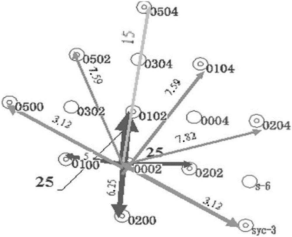
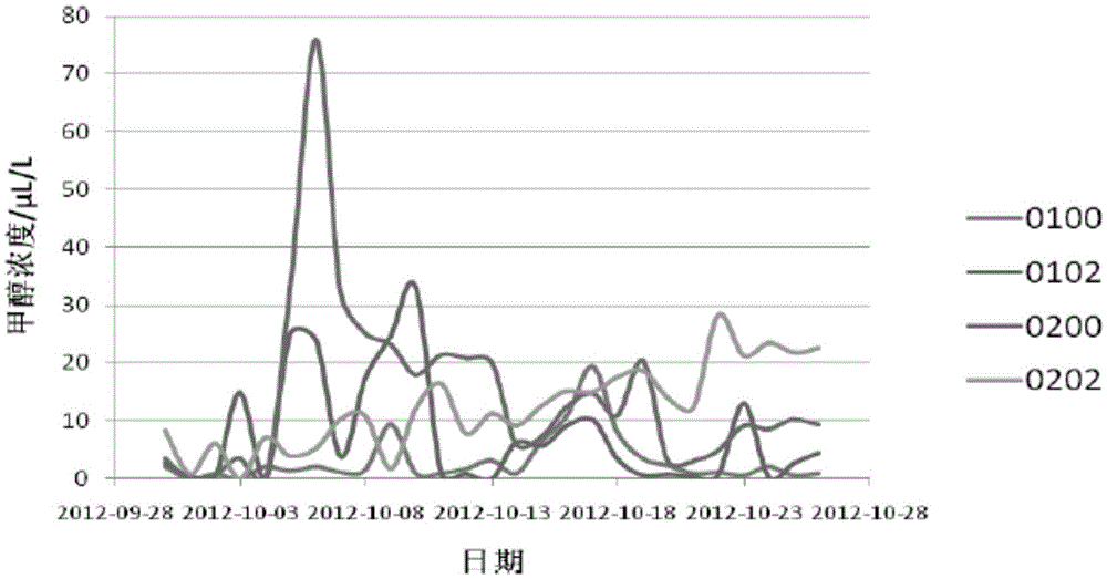
[0044] The C10 mining area of a certain uranium mine in Xinjiang adopted the method for monitoring the leaching range in uranium mining by in-situ leaching described in the present invention, and established a numerical model of the C10 mining area by using VisualModflow software. Methanol was used as a tracer in the test and production units Conduct cross-well tracer test. Specifically include the following steps:
[0045] Step (1) establishes numerical model with computer numerical simulation software, and it comprises 4 steps
[0046] (1.1) Model generalization;
[0047] Reasonably generalize the hydrogeological conditions of the in-situ leaching uranium mining test and production area, that is, transform the actual boundary properties, internal structure, permeability, hydraulic characteristics, and recharge and discharge concepts of the aquifer into basic concepts that are convenient for mathematical and physical simulations. Model,
[0048] (1.2) Model numericalizat...
Embodiment 2
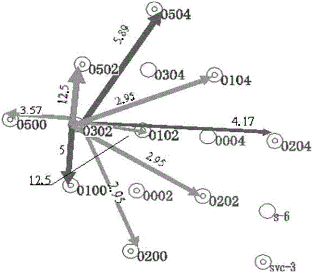
[0076] The C10 mining area of a certain uranium mine in Xinjiang adopted the method for monitoring the leaching range in uranium in situ leaching mining according to the present invention, and established a numerical model of the C10 mining area by using VisualModflow software. The production unit conducts cross-well tracer test. Specifically include the following steps:
[0077] Step (1) establishes numerical model with computer numerical simulation software, and it comprises 4 steps
[0078] (1.1) Model generalization;
[0079] Reasonably generalize the hydrogeological conditions of the in-situ leaching uranium mining test and production area, that is, transform the actual boundary properties, internal structure, permeability, hydraulic characteristics, and recharge and discharge concepts of the aquifer into basic concepts that are convenient for mathematical and physical simulations. Model,
[0080] (1.2) Model numericalization;
[0081] Convert the basic model of ste...
PUM
 Abstract
Description
Claims
Application Information