Optical fiber end face pumping coupler for optical fiber amplifier and fabrication method of optical fiber end face pumping coupler

A fiber amplifier and fiber end face technology, which is applied in the field of lasers, can solve the problems of special fiber bundle shape requirements, difficult bundle formation, and the inability to achieve high coupling efficiency of signal laser and pump laser at the same time, achieving high coupling efficiency, high Effect of Pump Optical Coupling Efficiency

Active Publication Date: 2016-06-01
NAT UNIV OF DEFENSE TECH
View PDF6 Cites 14 Cited by
  • Summary
  • Abstract
  • Description
  • Claims
  • Application Information

AI Technical Summary

Problems solved by technology

[0005] The object of the present invention is to provide a kind of optical fiber end-pump coupler for optical fiber amplifier and manufacturing method thereof, this invention solves the coupling efficiency of signal laser and pump laser in the end-face or side-pum

Method used


Image

  • Optical fiber end face pumping coupler for optical fiber amplifier and fabrication method of optical fiber end face pumping coupler
  • Optical fiber end face pumping coupler for optical fiber amplifier and fabrication method of optical fiber end face pumping coupler
  • Optical fiber end face pumping coupler for optical fiber amplifier and fabrication method of optical fiber end face pumping coupler

Examples


Embodiment 1

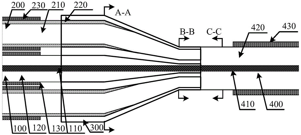
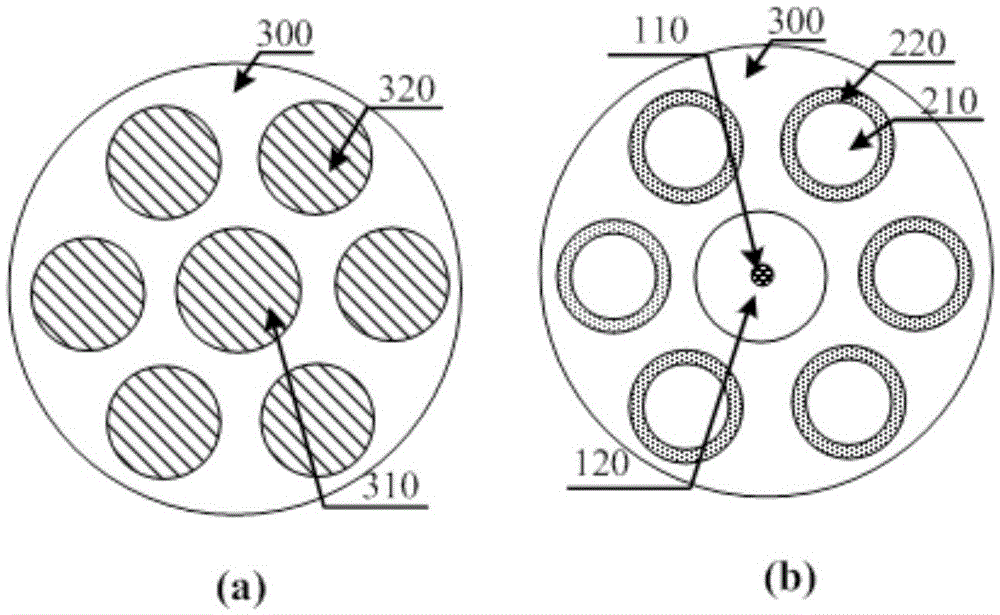
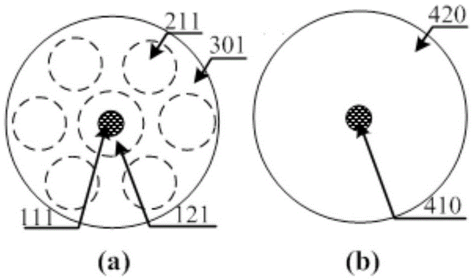
[0053] Such as Figure 1~3 As shown, this embodiment provides a fiber end-pump coupler for a fiber amplifier, and the coupler is a (6+1)×1 fiber end-pump coupler. The coupler includes a fusion cone input fiber bundle, a glass tube 300 and an output fiber 400 . The fusion cone input fiber bundle includes one input signal fiber 100 arranged on the central axis and six pumping fibers 200 uniformly distributed around the periphery of the input signal fiber 100 . Wherein the input signal fiber 100 comprises a signal fiber core 110, a signal cladding 120 wrapped on the outer wall of the signal fiber core 110 and a signal coating 130 wrapped on the outer wall of the signal cladding 120, the structures of the pump fiber and the output fiber are the same as Similar to this, the optical fiber structures used in other embodiments are also similar to this, and will not be described in detail below. Each pumping fiber 200 includes a pumping fiber core 210 , a pumping fiber cladding 220 a...

Embodiment 2

[0066] see Figure 4~6 , this embodiment is a (10+1)×1 fiber end-face coupler. The coupler includes a fused cone input fiber bundle, a glass tube 300 and an output fiber 400 . The taper input optical fiber bundle includes one input signal optical fiber 100 at the central axis and ten input pump optical fibers 200 evenly distributed around the periphery of the input signal optical fiber 100 .

[0067]The input signal fiber 100 includes a signal fiber core 110 , a signal fiber cladding 120 and a signal fiber coating 130 . Each input pump fiber 200 includes a pump fiber core 210 , a pump fiber cladding 220 and a pump fiber coating 230 . The output fiber 400 includes an output fiber core 410 , an output fiber inner cladding 420 and an output fiber coating 430 . Figure 5 (a) is a cross-sectional view of the glass tube used in this embodiment, where 310 is the signal fiber air hole, and 320 is the pump fiber air hole. Figure 5 (b) is Figure 4 The cross-sectional view of A-A ...


PUM

PropertyMeasurementUnit
Outer diameteraaaaaaaaaa
Lengthaaaaaaaaaa
Diameteraaaaaaaaaa

Abstract

The invention provides an optical fiber end face pumping coupler for an optical fiber amplifier and a fabrication method of the optical fiber end face pumping coupler. According to the method, conical input optical fibers after being tapered or corroded are combined by using a glass tube, and then the conical input optical fibers are fused with output optical fibers; and a fiber core of an input signal optical fiber is not needed to be tapered, the diameters of the fiber cores of the input optical fibers and the fiber cores of the output optical fibers can be ensured to be basically consistent, thus, the coupler can be suitable for various modes of signal light, and relatively high coupling efficiency can be achieved.

Description

technical field [0001] The invention relates to the field of laser technology, in particular to an optical fiber end-face pumping coupler used for an optical fiber amplifier and a manufacturing method thereof. Background technique [0002] Fiber lasers, due to their high conversion efficiency, good beam quality, compact structure, easy heat dissipation, and good working stability, have been widely used in industrial processing, medical and health, and national defense and military fields. In recent years, with the maturity of double-clad fiber pumping technology and the improvement of fiber manufacturing process, the output power of fiber lasers has also been continuously improved. At present, the main oscillator power amplifier (MOPA) structure is mainly used in high-power fiber lasers to increase the laser output power. This structure usually consists of an oscillator and a one-stage amplifier or more amplifiers. The role of the fiber pump coupler is to efficiently couple...

Claims


Application Information

Patent Timeline
IPC IPC(8): H01S3/094G02B6/255
CPCG02B6/255H01S3/094019H01S3/094038H01S3/094042
Inventor 周旋风陈子伦王泽锋侯静奚小明雷成敏许晓军
Owner NAT UNIV OF DEFENSE TECH
Why Eureka
Try Eureka