
Power system control

A power system and subsystem technology, applied in the field of monitoring power system devices, to achieve the effect of reducing the communication burden

Active Publication Date: 2016-06-01
THE UNIV OF BIRMINGHAM
View PDF3 Cites 0 Cited by
  • Summary
  • Abstract
  • Description
  • Claims
  • Application Information

AI Technical Summary

Problems solved by technology

The problem with this approach is that it places unacceptable demands on the performance of the measuring instrument and the speed of data communication

Method used


Image

  • Power system control
  • Power system control
  • Power system control

Examples


Embodiment Construction

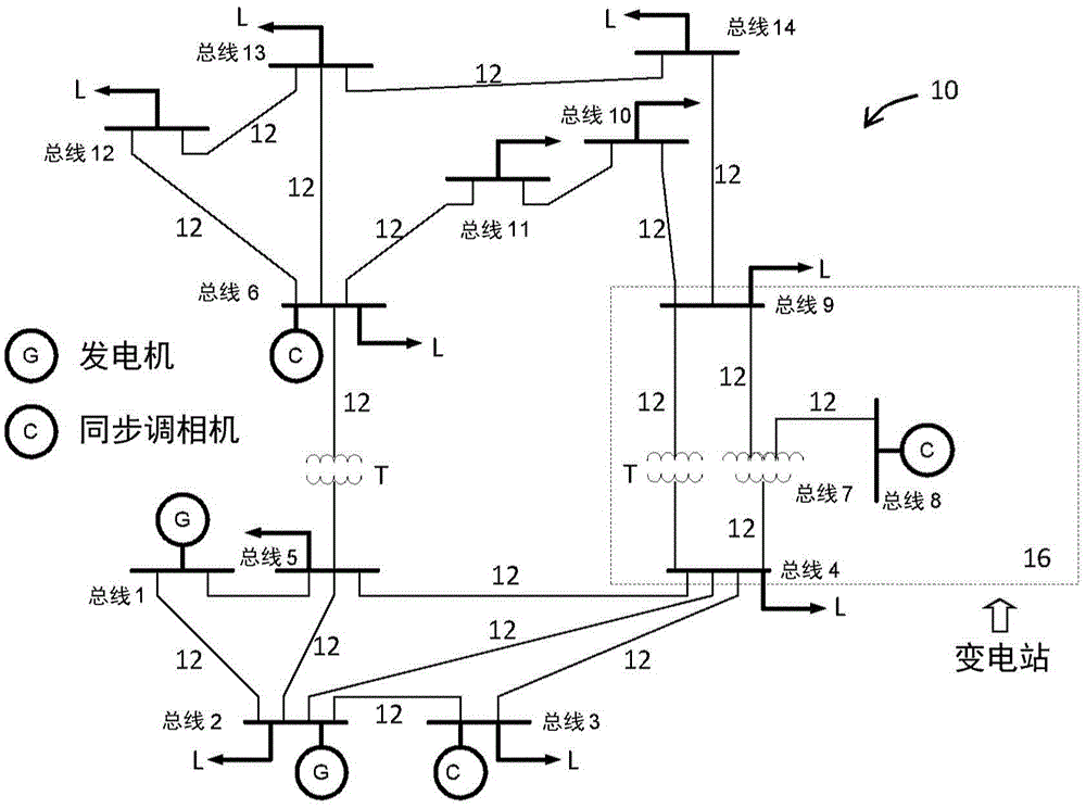
[0035] Embodiments described below include a practical method for performing transient state estimation of a power grid that allows accurate state estimation during periods of system disturbance. this includes figure 1 An example of transient estimation of the grid type shown in , but the method is not limited to this example, but can be applied to various grid configurations. Furthermore, the embodiments describe using a phasor measurement unit (PMU) to obtain synchronization measurements. Simultaneous measurements can be provided by a large number of instruments. A PMU is one example that is currently being used in electrical grids. A PMU is a device capable of providing synchronized measurements of electrical waves using a common time source. However, any other known or still developing device capable of providing synchronized measurement samples at a high sampling frequency may be used.

[0036] An overview of the process is in Figure 10 is shown in the flowchart and...


PUM


Abstract

The present invention relates to a method of controlling power flows and / or voltages in a power system. The method comprises monitoring conditions of voltage and / or current at a set of system locations for a scanning cycle of synchronised measurements. The scanning cycle comprises a series of time steps in which instantaneous sample measurements of voltage and / or current are taken. The monitoring provides data comprising the instantaneous sample measurements for a complete scanning cycle. A transient state estimation is determined based on the data for two or more sequential time steps. The transient state estimation includes an estimation of a non-sinusoidal voltage or current waveform caused by a disturbance to the power system. The method further includes forming a snapshot that includes instantaneous voltages, current flows and power flows of the power system. The method further includes making an adjustment to mitigate the effect of the disturbance. The invention also resides in a power system comprising a plurality of synchronised measurement units at locations in the power system. Each measurement unit is configured to obtain sample data over a synchronised scanning cycle comprising a series of time steps in which instantaneous sample measurements of voltages and / or currents are taken, and to transmit the instantaneous sample data for a complete scanning cycle after completion of the cycle. A transient state estimator is configured to receive and analyse the sample data to determine a transient state estimation based on the data for two or more sequential time steps. The transient state estimation includes an estimation of a non-sinusoidal voltage or current waveform caused by a disturbance to the power system. At least one power device adjusts an amount of power supplied to and / or drawn from the power system to mitigate the effect of the disturbance.

Description

technical field [0001] The present invention relates to a device, method and computer program for monitoring and control of a power system. More specifically, the present invention relates to controlling power flow and voltage in a power system in the event of system disturbances. Background technique [0002] A power system or grid typically includes multiple power buses interconnected by transmission lines. figure 1 An example of an IEEE14-bus system 10 is shown, in which the buses Bus1 , Bus2 , . . . , Bus14 are interconnected by transmission lines 12 . Generators G provide power to some buses (such as Bus1 and Bus2), while loads L draw power from some buses. In addition, some buses have synchronous condensers C for generating or absorbing the energy needed to regulate the voltage or improve the power factor in the grid. In addition, if figure 1 As shown in , some transmission lines 12 may include a transformer T for stepping down or boosting the voltage between the b...

Claims


Application Information

Patent Timeline
Patent Type & Authority Applications(China)
IPC IPC(8): H02J13/00G01R19/25
CPCG01R19/2513Y04S10/30Y04S40/12H02J13/00002H02J13/00006H02J13/00034Y02B90/20Y02E60/00Y04S10/00Y04S10/22Y04S20/222Y02E40/70Y02B70/3225
Inventor 张小平杨翾
Owner THE UNIV OF BIRMINGHAM
Learn More