
Sewage sand-filtering equipment

A sewage and sand filtering technology, which is applied in the direction of filtration and separation, fixed filter elements, chemical instruments and methods, etc., can solve the problems of increased time and cost of sewage treatment, and achieve improved mixing efficiency, convenient mixing, and improved removal The effect of sand efficiency

Inactive Publication Date: 2016-06-08
山东艾克赛尔机械制造有限公司
View PDF9 Cites 5 Cited by
  • Summary
  • Abstract
  • Description
  • Claims
  • Application Information

AI Technical Summary

Problems solved by technology

Due to the process of water flow, it must contain sediment, and the natural settlement method will greatly increase the time of sewage treatment, resulting in an increase in cost

Method used


Image

  • Sewage sand-filtering equipment
  • Sewage sand-filtering equipment

Examples


Embodiment 1

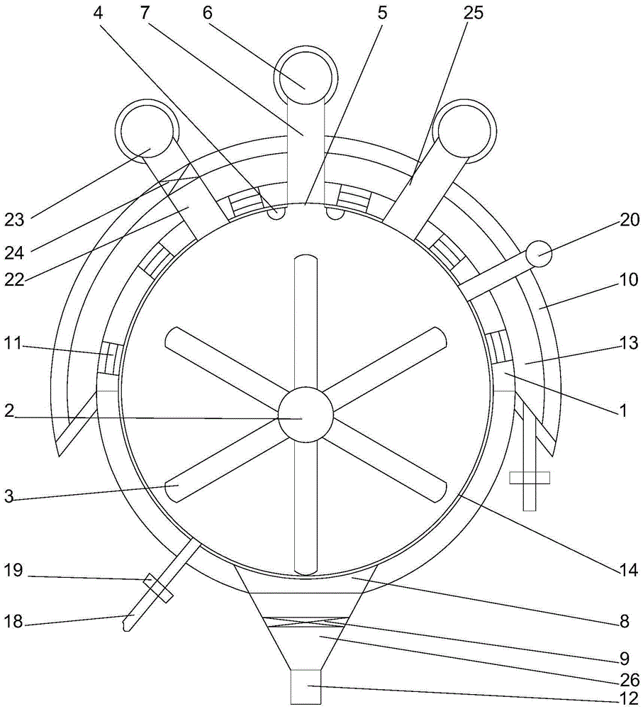
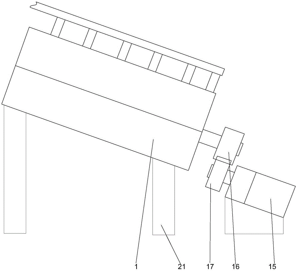
[0022] like figure 1 As shown in / 2, a sewage sand filter equipment includes a hollow cylindrical filter barrel 1 and a rotating shaft 2 arranged inside the filter barrel, and a water accumulation plate 10 is arranged on the filter barrel. The water accumulation plate has a semi-circular structure, and the water accumulation plate is set on the upper part of the filter barrel, and a water accumulation cavity 13 is formed between the water accumulation plate and the upper outer wall of the filter barrel, and the A through hole is provided on the end surface of the filter barrel facing the water accumulation plate, and the through hole communicates with the inner side of the filter barrel and the water accumulation chamber, and a filter screen is arranged inside the through hole 11. A drain valve is provided on the water accumulation plate, the axis of the rotating shaft and the axis of the filter bucket are staggered from each other, the axis of the rotating shaft is located be...

Embodiment 2

[0025] In this embodiment, on the basis of Embodiment 1, in order to conveniently control the pressure in the filter barrel, in this embodiment, preferably, a pressure relief valve 20 is provided on the filter barrel.

[0026] In order to facilitate the support of the filter bucket, in this embodiment, preferably, brackets 21 are provided respectively under the two ends of the filter bucket, and the heights of the upper ends of the two brackets are not equal. By making the heights of the two brackets unequal, the heights of the two ends of the filter barrel can be made different, so that the materials can move relatively under the action of gravity, thereby improving their mixing efficiency.

[0027] In this embodiment, when the sewage contains heavy metal ions, in order to facilitate the discharge of impurities in the sewage more fully, preferably, a dosing valve 25 is arranged on the filter barrel, and on the dosing valve A metering pump is provided. Meter the amount of flo...


PUM


Abstract

The invention discloses sewage sand-filtering equipment which comprises a hollow cylindrical filtering bucket and a rotating shaft arranged on the inner side of the filtering bucket. A water accumulation plate is arranged on the filtering bucket, is of a semicircular structure and is mounted on the upper portion of the filtering bucket in a sleeving manner, a water accumulation cavity is formed between the water accumulation plate and the outer wall of the upper portion of the filtering bucket, through holes are formed in an end face, opposite to the water accumulation plate, of the filtering bucket and communicated with the inner side of the filtering bucket and the water accumulation cavity, a filtering net is arranged on the inner side of each through hole, and a drain valve is arranged on the water accumulation plate. In the process of utilizing the rotating shaft to drive blades to rotate, sewage receives acting force of the blades; in the process when the blades rotate, when the sewage passes one sides of the through holes with the filtering nets under action of inertia force, water enters the water accumulation cavity through the filtering nets, silt is still remained in the filtering bucket, output through discharging holes and collected in a centralized manner when reaching one sides of the discharging holes.

Description

technical field [0001] The invention relates to a sewage sand filter equipment. Background technique [0002] Urban sewage contains a large amount of sediment. During the treatment process, structures such as grilles can only be used to filter large particles. The existing treatment method is mainly to settle the sewage, so that the sediment in it naturally falls and then further processing. Due to the process of water flow, it must contain sediment, and the natural settlement method will greatly increase the time of sewage treatment, resulting in an increase in cost. Contents of the invention [0003] The purpose of the present invention is to provide a kind of sewage sand filtering equipment, which can improve the problems existing in the prior art. During the rotation process of the blades driven by the rotating shaft, the sewage is subjected to the force of the blades. During the rotation process of the blades, the sewage is under the action of inertial force When pa...

Claims


Application Information

Patent Timeline
Patent Type & Authority Applications(China)
IPC IPC(8): B01D29/11B01D29/86B01D29/90
CPCB01D29/117B01D29/86B01D29/90
Inventor 张浩楠
Owner 山东艾克赛尔机械制造有限公司
Learn More