Micro blanking system for on-line processing of punch-die

A technology of micro-blanking and convex-concave dies, which is applied in the field of micro-blanking systems, can solve the problems of inability to process special-shaped dies, large taper of the side wall of the die, and low machining accuracy of the die, so as to reduce errors, increase the punching load, and The effect of high motion deviation absorption capacity

Active Publication Date: 2016-06-08
DALIAN UNIV OF TECH
View PDF5 Cites 2 Cited by
  • Summary
  • Abstract
  • Description
  • Claims
  • Application Information

AI Technical Summary

Problems solved by technology

However, this equipment uses the punch as the electrode to process the die, and the punch will be seriously lost during the processing. The copy processing die will have problems such as large taper of the die side wall and low processing accuracy of the die, and it cannot process complex shapes. Shaped mold

Method used


Image

  • Micro blanking system for on-line processing of punch-die
  • Micro blanking system for on-line processing of punch-die
  • Micro blanking system for on-line processing of punch-die

Examples


specific Embodiment 1

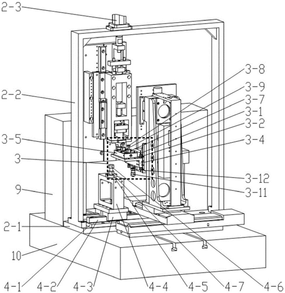
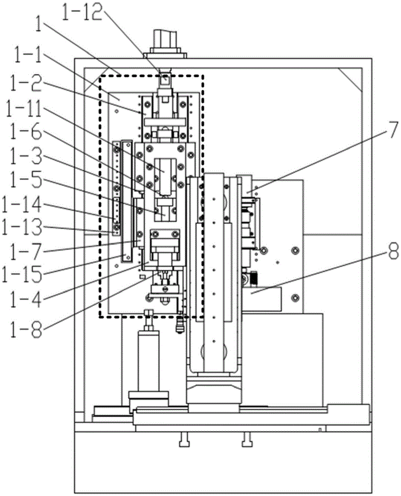
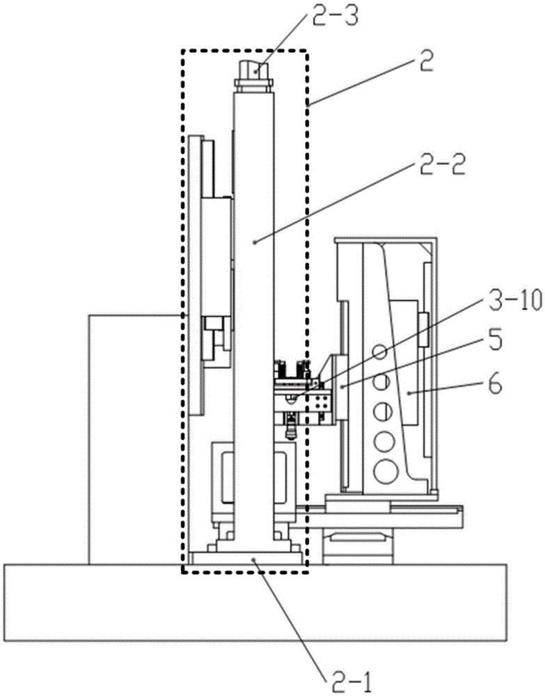
[0032] Specific embodiment one: as Figure 1-9 As shown, the micro-blanking system for online processing of punch and die described in this embodiment mainly includes a punch assembly 1, a door frame assembly 2, a die assembly 3, a bracket assembly 4, and a precision XYZ three-axis positioning assembly 5, Counterweight assembly 6, EDM spindle assembly 7, WEDG wire electrode grinding assembly 8, marble vertical board 9, marble countertop 10. The marble vertical plate 9 is a gantry structure, and is installed on the marble table 10 by screws to ensure that the verticality of the marble vertical plate 9 installation surface and the marble table 10 is 50 μm, and the punch assembly 1 and the electric spark spindle assembly 7 are respectively fixed on the On the left and right sides of the marble vertical plate installation surface, the door frame component 2 and the precision XYZ three-axis positioning component 5 are independently installed on the marble table 10, so that the X-ax...

specific Embodiment 2

[0033] Specific embodiment 2: The punch linear guide 1-2 used in the punch assembly 1 can choose the HGH30HA ultra-precision linear guide in Taiwan HIWIN, and the grating ruler used for the linearity up to 2 μm can choose the LS400170 produced by Germany Heidenhain .

specific Embodiment 3

[0034] Specific embodiment three: as Figure 1~3 As shown, the gantry assembly 2 of the micro-blanking system in this embodiment includes a gantry bottom plate 2-1, a gantry main body 2-2 and a linear actuator 2-3; wherein the gantry bottom plate 2-1 is installed on a marble table 10, the door frame main body 2-2 is a door-shaped frame structure, which is spliced ​​by two vertical plates and a horizontal plate. The main body of the door frame 2-2 is fixed to the door frame bottom plate 2- 1 and make the main body 2-2 of the door frame straddle the marble table 10, the installation surface of the top horizontal plate is basically parallel to the marble vertical board 9 and the marble table 10, and the linear actuator 2-3 is installed on the top of the main body 2-2 of the door frame. and make the execution feed direction of the linear actuator 2-3 perpendicular to the marble table top 10, the execution end of the linear actuator 2-3 is connected and fastened with the push rod c...


PUM


Abstract

The invention belongs to the field of manufacturing of precision machinery and provides a micro blanking system for on-line processing of a punch-die. A punch assembly and an electric spark spindle assembly are fixed on a vertical marble plate; a power source portal frame assembly is separately mounted on a marble platform surface and connected to the punch assembly; a support frame assembly for bearing force is mounted on a portal frame base plate of the portal frame assembly; a precise XYZ three-axis positioning assembly is mounted on the marble platform surface; a die assembly and a wire electrical discharge grinding (WEDG) assembly are mounted on a z axis of the precise XYZ three-axis positioning assembly; and a counterweight assembly is mounted on the Z axis and balanced with the die assembly and the WEDG assembly in weight. The punch assembly adopts a spherical surface contact rigid connection structure of an ultraprecise linear guide rail and a high-load linear actuator, and the die assembly adopts a floating structure based on a precise linear guide rail. The micro blanking system realizes on-line processing, trimming and center alignment of special-shaped punch-dies as well as blanking, high-load blanking, stretching and other various processes of micro special-shaped parts.

Description

technical field [0001] The invention belongs to the field of precision machinery manufacturing and relates to a micro-blanking system suitable for on-line processing of convex and concave dies. Background technique [0002] Most of the existing micro-stamping equipment uses precision guide posts and guide sleeves to realize the alignment of the convex and concave dies, so the processing and assembly precision of the dies is high, and disassembly is difficult. Moreover, due to the difficulty of mold centering, most micro-blanking molds cannot realize stamping of special-shaped parts. Micro-EDM is a special processing method that utilizes the electric erosion effect produced by the pulse discharge between the two poles immersed in the working fluid to erode conductive materials. It has the advantages of high forming precision and wide range of applicable materials. [0003] Aiming at the problems of existing micro-stamping equipment and combining the advantages of micro-EDM, ...

Claims


Application Information

Patent Timeline
IPC IPC(8): B21D28/14B23H1/00B23H1/04B23H11/00B23H7/26
CPCB21D28/14B23H1/00B23H1/04B23H7/26B23H11/003
Inventor 刘新杨晓龙周诗宁陈发泽黄帅余祖元李剑中邢英杰
Owner DALIAN UNIV OF TECH
Why Eureka
Try Eureka