Die assembly upsetting and forging machine and working method thereof

An upsetting machine and upsetting technology, which is applied in the field of upsetting machines, can solve problems such as the complex structure of upsetting machines, the inability to upsetting formed parts, and the difficulty in high-speed upsetting, so as to improve the accuracy of equipment, improve driving reliability, The effect of reducing the failure rate

Inactive Publication Date: 2016-06-08
杨东佐
View PDF5 Cites 31 Cited by
  • Summary
  • Abstract
  • Description
  • Claims
  • Application Information

AI Technical Summary

Problems solved by technology

These two types of upsetting machines mostly use wire rods as raw materials for upsetting at present. Therefore, before upsetting, the wire rods must be cut into blanks according to the size requirements of the formed parts. In order to realize this process, upsetting machines need separate The installation of material cutting device and material clamping and conveying device makes the structure of the whole heading machine complex, and requires high cooperation among cutting material, upsetting and ejection, and it is difficult to realize high-speed upsetting, and debugging is particularly troublesome
[0006] For the multi-die and multi-blow upsetti

Method used


Image

  • Die assembly upsetting and forging machine and working method thereof
  • Die assembly upsetting and forging machine and working method thereof
  • Die assembly upsetting and forging machine and working method thereof

Examples


Embodiment 1

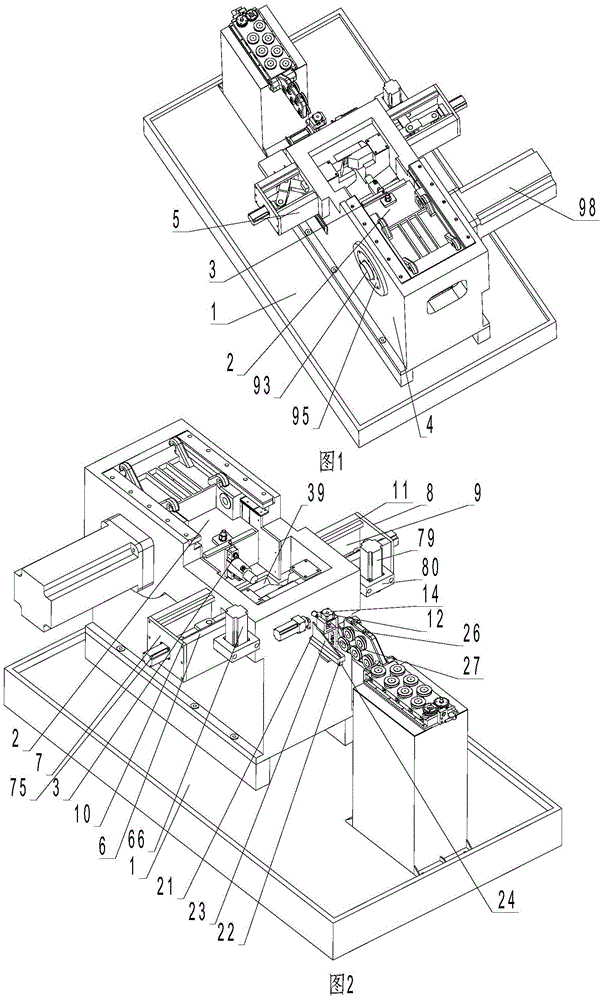
[0102] Such as figure 1 , figure 2 , Figure 9 As shown, a die-clamping upsetting machine for upsetting steel balls includes a body 1, a large slider 2 mounted on the body 1 that can slide back and forth, a die assembly 3 mounted on the large slider 2 and a large drive The large slide block drive mechanism that slide block 2 slides back and forth, the main mold assembly 3, the wire feeding mechanism that is installed on the body 1.

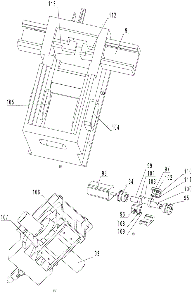
[0103] Such as figure 1 , figure 2 As shown, the body 1 includes a frame body 4 and a frame seat 5, and the frame seat 5 includes a frame body 6, an end plate 7, and an end plate 8, and the frame body 6 has an accommodating cavity 9, and the two sides of the accommodating cavity 9 The end portion has an opening 10 and an opening 11 , the end plate 7 is fixed on the base body 6 at the opening 10 , and the end plate 8 is fixed on the base body 6 at the opening 11 . Both ends of the frame body 6 protrude from the frame body 4 .

[0104] There a...

Embodiment 2

[0139] Such as Figure 10 to Figure 14 As shown, the difference from Embodiment 1 is that three stations are provided on the frame body 151 , a cutting station 152 , an upset forging station 153 , and an upset forging station 154 .

[0140] Such as figure 1 , Figure 4 , Figure 5 , Figure 9 As shown, the main mold assembly 3 includes a main mold base 155 fixed on the frame body 151, a trimming sleeve 156, and a mold clamping assembly. Corresponding to the trimming position 152 of the machine body 1, a trimming cover installation hole 157 is provided on the main mold base 155 . The shearing sleeve 156 is installed in the mounting hole 157 of the shearing sleeve. There is no upsetting die mounting hole on the main mold base 155, and no ejector mechanism is needed on the main mold assembly 170 side. .

[0141] The first installation space is set on the first clamping base 162 and opens towards the second clamping base 163, and penetrates the first groove 158 of the first...

Embodiment 3

[0155] Such as Figure 15 to Figure 19 As shown, the difference from Embodiment 2 is that, at the trimming position 201, the machine body 202 is also provided with a pneumatic feeding mechanism. The pneumatic blowing mechanism includes a cylinder support 203, a cylinder 204, and a blowing part 205. Cylinder support 203 is fixed on the top of the body 202 of cutting material position 201, and cylinder 204 is fixed on the top of cylinder support 203, and the fixed piston rod 206 with the piston of cylinder 204 passes cylinder support 203 and blows material 205 and fixes. The axis of the piston rod 206 of the cylinder 204 is perpendicular to the axis of the shear sleeve 207 .

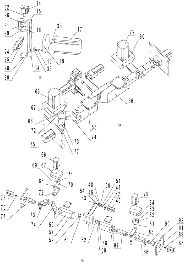
[0156] The first mold clamping driving mechanism includes a first servo motor 209 that only drives the translation of the first mold clamping base 208 , a mounting base 210 , a first driving member 212 , and a first driving slider 214 . The first drive member 212 includes a first drive disc 213, a first ...


PUM


Abstract

The invention discloses a die assembly upsetting and forging machine and a working method thereof. The die assembly upsetting and forging machine comprises a machine body, a punch die assembly, a punch die assembly driving mechanism, a feeding mechanism and a material shearing sleeve; the machine body is provided with a die assembly device; the die assembly device comprises a first die assembly base and a second die assembly base; a first installation space is arranged on the side face, close to the second die assembly base, of the first die assembly base; a second installation space is arranged on the side face, close to the first die assembly base, of the second die assembly base; and the die assembly upsetting and forging machine is further provided with a first die assembly driving mechanism for driving the first die assembly base to horizontally move and a second die assembly driving mechanism for driving the second die assembly base to horizontally move. The working method comprises the steps that displacement whole-circle material shearing and material transferring of station parts are achieved through horizontal movement of the die assembly device, and then upsetting and forging are conducted. According to the working method, an independent material shearing mechanism and an independent material clamping and blank transferring mechanism are omitted, and the functions of die assembly material shearing and die assembly upsetting and forging and the function of a clamp are achieved.

Description

technical field [0001] The invention relates to an upsetting machine and its working method, in particular to a cold heading and upsetting machine in which a wire is fed into the upsetting machine by a feeding mechanism to be sheared to form a billet and the working method thereof. Background technique [0002] The upsetting machine is a device that uses the back and forth motion of the large slider to upset the blank in the main die through the die. [0003] Upsetting machine is mainly composed of body, die assembly, large slider drive mechanism, main mold, ejector mechanism, feeding mechanism and shearing mechanism. [0004] In the traditional upsetting machine, the die seat of the die assembly is fixed with the large slider, and the die seat of the main die assembly is fixed on the corresponding machine body. The upsetting machine with this structure must be equipped with a separate cutting mechanism and clamp Only the tong mechanism can realize the displacement of the s...

Claims


Application Information

Patent Timeline
IPC IPC(8): B21J9/06B21J13/02B21J13/08B21K27/02B21K27/06
CPCB21J9/06B21J13/02B21J13/085B21K27/02B21K27/06
Inventor 杨东佐
Owner 杨东佐
Why Eureka
Try Eureka