Precise multi-station automatic valve chamfering machine and machining method thereof

A multi-station, chamfering machine technology, applied in metal processing, metal processing equipment, machine tools suitable for grinding workpiece edges, etc., can solve the problems of low processing efficiency, reducing workpiece processing accuracy, increasing tool loss, etc. Achieve the effects of saving processing time, ensuring processing accuracy and improving processing efficiency

Active Publication Date: 2016-06-08
GUANGDONG HESHI AUTOMATION TECH CO LTD
View PDF4 Cites 5 Cited by
  • Summary
  • Abstract
  • Description
  • Claims
  • Application Information

AI Technical Summary

Problems solved by technology

However, because some workpieces need to be chamfered on both sides of the workpiece, workers need to repeatedly disassemble and install the workpiece, and when processing the same workpiece, it is necessary to perform tool setting on the workpiece twice, which makes the processing efficiency low and reduces the processing of the workpiece. Accuracy, but also increases the loss of the tool
And because the workers always need to disassemble and install the workpiece, that is to say, each operator needs to be equipped with a chamfering machine. When workpieces need to be produced in large quantities, a large number of processing equipment is required, which makes the machine occupy a large space. , At the same time, due to the large noise during processing the workpiece, it will have a great impact on the hearing of the operator
In summary, it can be seen that the traditional chamfering machine causes a lot of waste of manpower, material resources and financial resources, and the processing efficiency is also low.

Method used


Image

  • Precise multi-station automatic valve chamfering machine and machining method thereof
  • Precise multi-station automatic valve chamfering machine and machining method thereof
  • Precise multi-station automatic valve chamfering machine and machining method thereof

Examples


Embodiment Construction

[0036] Example of piston precision multi-station automatic chamfering machine:

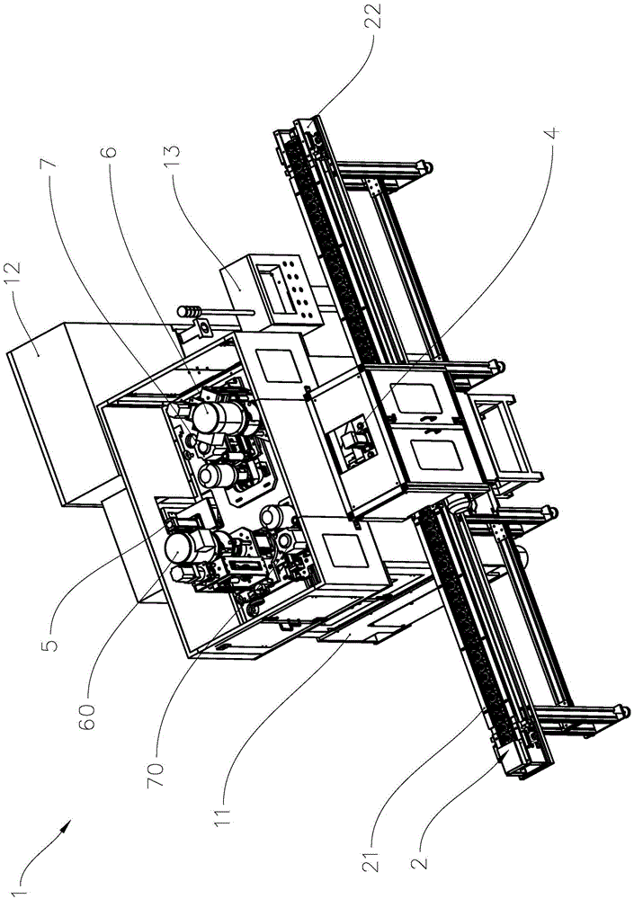
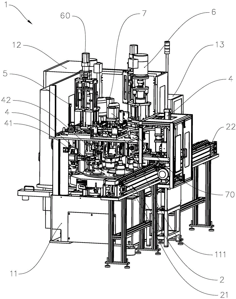
[0037] refer to figure 1 and figure 2 , figure 1 It is the structural diagram of the piston precision multi-station automatic chamfering machine of the present invention, figure 2 It is a structural diagram of the precision multi-station automatic chamfering machine for pistons of the present invention with some components omitted. Piston precision multi-station automatic chamfering machine 1 includes body 11, distribution box 12, console 13, belt conveyor 2, rotating device 3, loading and unloading device 4, turning device 5, first inner diameter chamfering device 6, The second inner diameter chamfering device 60 , the first outer diameter chamfering device 7 and the second outer diameter chamfering device 70 . The fuselage 11 is provided with an upper partition 111, the distribution box 12 is installed on the first side of the fuselage 11, the console 13 is installed on the second side of ...


PUM


Abstract

The invention provides a precise multi-station automatic valve chamfering machine and a machining method thereof. The precise multi-station automatic valve chamfering machine comprises a machine body, a distribution cabinet and a control console. The precise multi-station automatic valve chamfering machine also comprises a belt conveying device, a rotating device, a loading and unloading device, a turnover device, a first inner diameter chamfering device, a second inner diameter chamfering device, a first outer diameter chamfering device and a second outer diameter chamfering device which are arranged on the machine body, wherein the belt conveying device is arranged on the machine body; the loading and unloading device is arranged between a feeding line and a discharging line of the belt conveying device; and the first inner diameter chamfering device, the first outer diameter chamfering device, the second inner diameter chamfering device and the second outer diameter chamfering device are distributed at the two sides of a connecting line of the loading and unloading device and the turnover device. The precise multi-station automatic valve chamfering machine and the machining method of the precise multi-station automatic valve chamfering machine have the characteristics of high efficiency, high machining precision, capability of machining multiple workpieces at the same time and the like and effectively saves lots of labor.

Description

technical field [0001] The invention relates to the field of mechanical processing, in particular to a precision multi-station automatic chamfering machine for pistons and a processing method thereof. Background technique [0002] When chamfering the existing cylindrical and circular workpieces, it is generally necessary to place the workpiece in the clamping jaws of the lathe or milling machine, and then pull the handle to make the clamping jaws clamp the workpiece. The milling cutter chamfers the workpiece. However, because some workpieces need to be chamfered on both sides of the workpiece, workers need to repeatedly disassemble and install the workpiece, and when processing the same workpiece, it is necessary to perform tool setting on the workpiece twice, which makes the processing efficiency low and reduces the processing of the workpiece. Accuracy, but also increased the loss of the tool. And because the workers always need to disassemble and install the workpiece, ...

Claims


Application Information

Patent Timeline
Patent Type & Authority Applications(China)
IPC IPC(8): B24B9/04B23Q7/02B24B41/06
CPCB23Q7/02B24B9/04B24B41/06
Inventor 吴少威黄伟华朱惠德
Owner GUANGDONG HESHI AUTOMATION TECH CO LTD
Why Eureka
Try Eureka