Multi-stage varied-diameter screw oil-water separator

A technology of oil-water separator and three-stage spiral, which is applied in the direction of liquid separation, separation methods, chemical instruments and methods, etc., can solve problems such as difficult and efficient separation, and achieve the effect of enhancing oil-water two-phase separation and reducing cross-sectional area

Active Publication Date: 2016-06-15
NORTHEAST GASOLINEEUM UNIV
View PDF10 Cites 16 Cited by
  • Summary
  • Abstract
  • Description
  • Claims
  • Application Information

AI Technical Summary

Problems solved by technology

It is difficult for the existing separation equipment to achieve efficient separa

Method used


Image

  • Multi-stage varied-diameter screw oil-water separator
  • Multi-stage varied-diameter screw oil-water separator
  • Multi-stage varied-diameter screw oil-water separator

Examples


Embodiment Construction

[0025] The present invention will be further described below in conjunction with accompanying drawing:

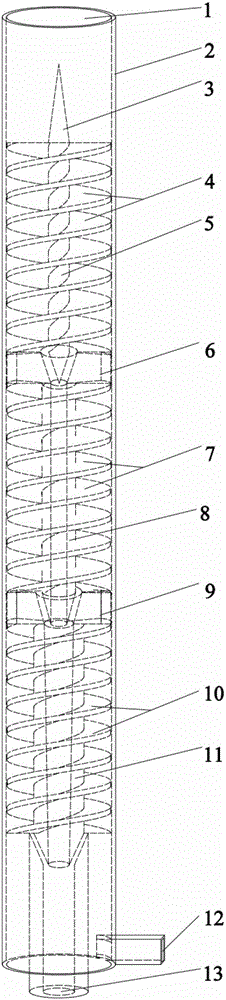
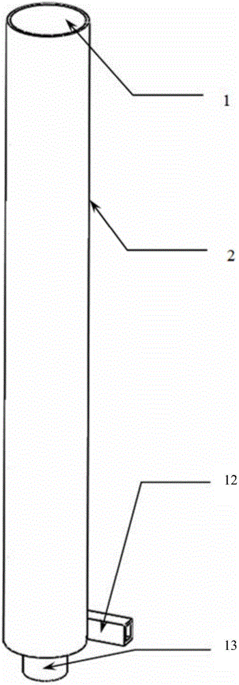
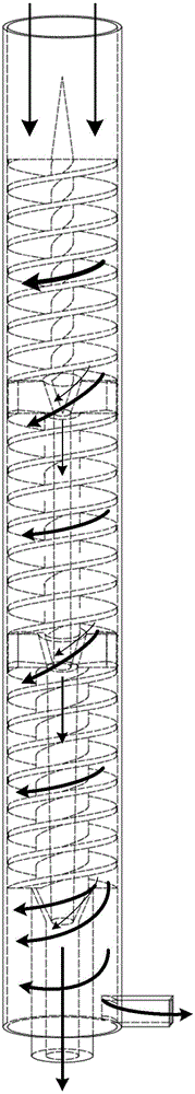
[0026] Depend on Figure 1 to Figure 10 As shown, this kind of multi-stage variable-diameter spiral oil-water separator has a wall tube 2 and an underflow tube 12, and the bottom flow tube 12 is tangentially connected to the bottom end of the wall tube 2. Its unique feature is that the upper end opening of the wall tube 2 is Inlet 1; contains at least a secondary separation unit in the wall tube 2. In practice, the entrance can be axial, inclined or tangential, and the inclined or tangential entrance can be single or multi-entry. This patent takes the axial entrance and the three-stage separation unit in the wall cylinder as an example. .

[0027] The first-stage separation unit is composed of a first-stage spiral piece 4, a first-stage inner tube 5, and a first-stage sub-fluid 6 after being connected. The inner wall of the wall tube 2, the first-stage spiral piece, and t...


PUM


Abstract

The invention discloses a multi-stage varied-diameter screw oil-water separator capable of realizing efficient separation aiming at separating mediums under high-viscosity and small-particle states. The multi-stage varied-diameter screw oil-water separator is characterized in that a wall barrel at least comprises two stages of separating units; each separating unit consists of a spiral sheet, an inner pipe and a flow division body which are connected; a spiral runner consists of the wall barrel, the spiral sheet and the inner pipe; each stage of spiral sheet is independent; a flow stabilizing cone is fixed at the upper end of one inner pipe; an inverted frustum-shaped circular pipe channel is fixed in the center of the flow division body through two fan-shaped connection bodies, and the diameters are gradually reduced along the axial direction; the tail ends of the inner pipes are inversely frustum-shaped and are matched with the inner circular pipe channels in the flow division bodies, with an annular overflow space; the outer diameter of each inner pipe is gradually increased, and the circular pipe channels of the corresponding stages are enlarged according to the same ratio; the tail end of the inner pipe of the last stage is connected to the top end of an overflow pipe; and the overflow pipe is matched with the tail end of the inner pipe of the last stage, so that an annular overflow space with a gradually reduced diameter is formed.

Description

technical field [0001] The invention relates to a two-phase separation treatment device applied in the fields of petroleum, chemical industry, environmental protection and the like. Background technique [0002] At present, the rapid separation methods used for two-phase (oil-water two-phase as an example) mainly include centrifugal separation (such as cyclone separation, spiral separation, etc.), air flotation, filtration and membrane separation. Cyclone separation has the advantages of small equipment size, etc., but it has limited ability to remove fine oil droplets, and the space for effective separation of mass transfer and exchange between two phases in the cyclone is small, mainly concentrated in the inlet jet and the cyclone chamber, and As the loss along the cyclone increases, the effective separation speed gradually decreases and the separation time is shorter; air flotation can adapt to a smaller range of oil concentration changes; filtration can better achieve th...

Claims


Application Information

Patent Timeline
IPC IPC(8): B01D17/038
CPCB01D17/0217
Inventor 蒋明虎徐保蕊赵立新张晓光曹喜承黄雯雯
Owner NORTHEAST GASOLINEEUM UNIV
Why Eureka
Try Eureka