Internally cooled airfoil for a rotary machine

a technology of rotary machines and airfoils, which is applied in the direction of manufacturing tools, foundry patterns, moulding apparatus, etc., can solve the problems of reduced cycle efficiency and increased emission levels, and achieve the effect of enhancing cooling especially in the trailing edge region

Inactive Publication Date: 2018-02-13
ANSALDO ENERGIA IP UK LTD
View PDF26 Cites 1 Cited by
  • Summary
  • Abstract
  • Description
  • Claims
  • Application Information

AI Technical Summary

Benefits of technology

[0008]It is an object of the invention to provide an internally cooled casted airfoil for a rotary machine, preferably a gas turbine engine comprising the features as discussed before by referring to the document U.S. Pat. No. 7,946,815 B2 as the closest state of the art wherein the cooling especially in the trailing edge region shall be enhanced by avoiding a huge material accumulation especially at the pressure sided wall to avoid any further stresses.

Problems solved by technology

Higher engine gas temperature have led to increased cooling bleed requirements resulting in reduced cycle efficiency and increased emission levels.
As the trailing edge is subject to a very high heat load, the suction side cooling channel has to provide sufficient air to keep the trailing edge temperatures sufficiently low.

Method used


Image

  • Internally cooled airfoil for a rotary machine
  • Internally cooled airfoil for a rotary machine
  • Internally cooled airfoil for a rotary machine

Examples


Embodiment Construction

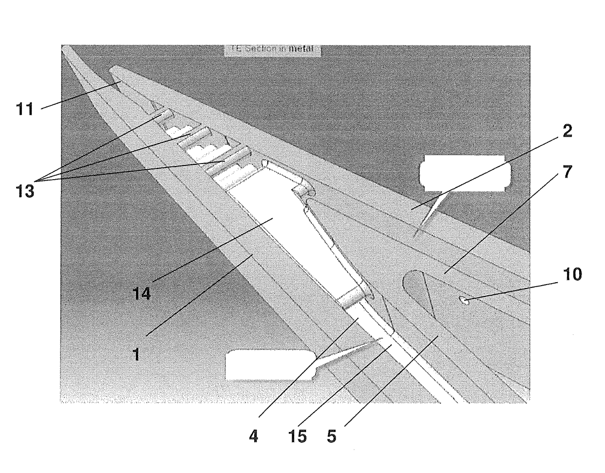
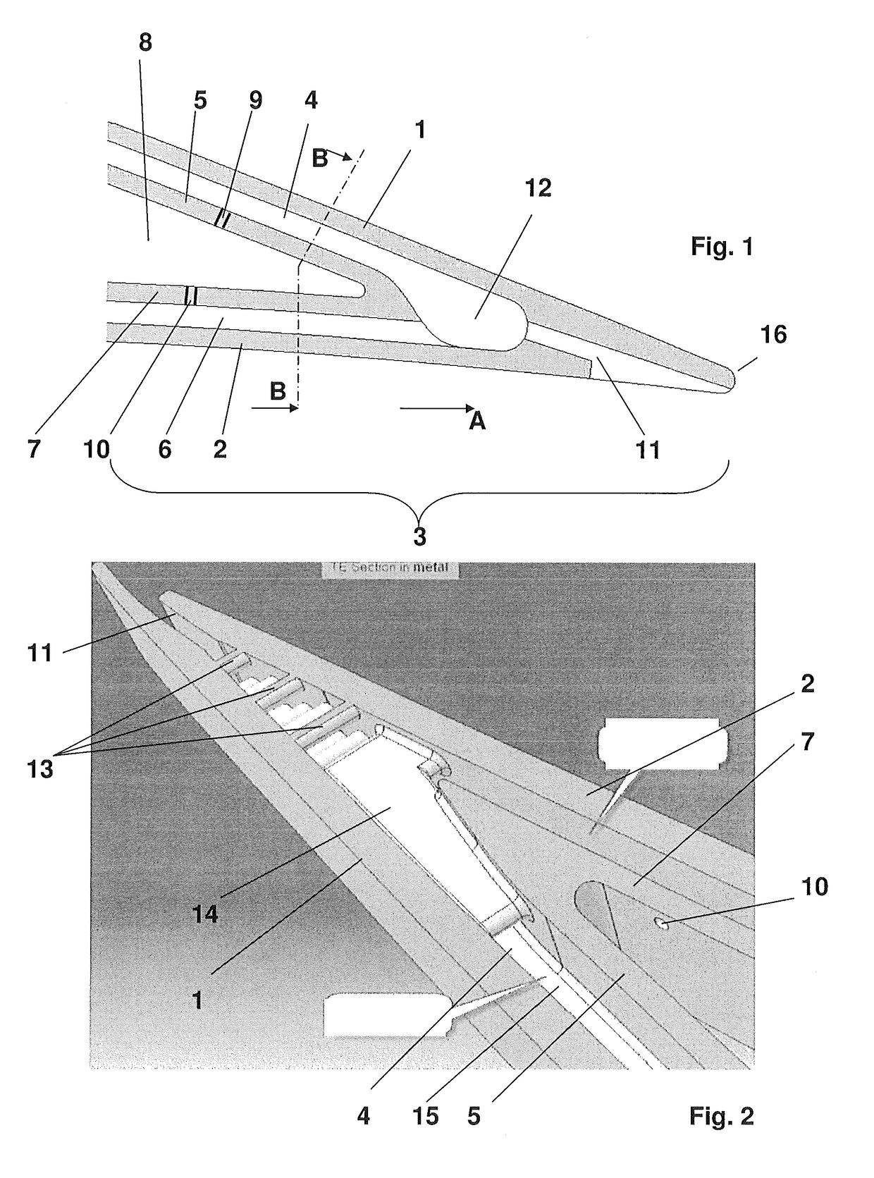
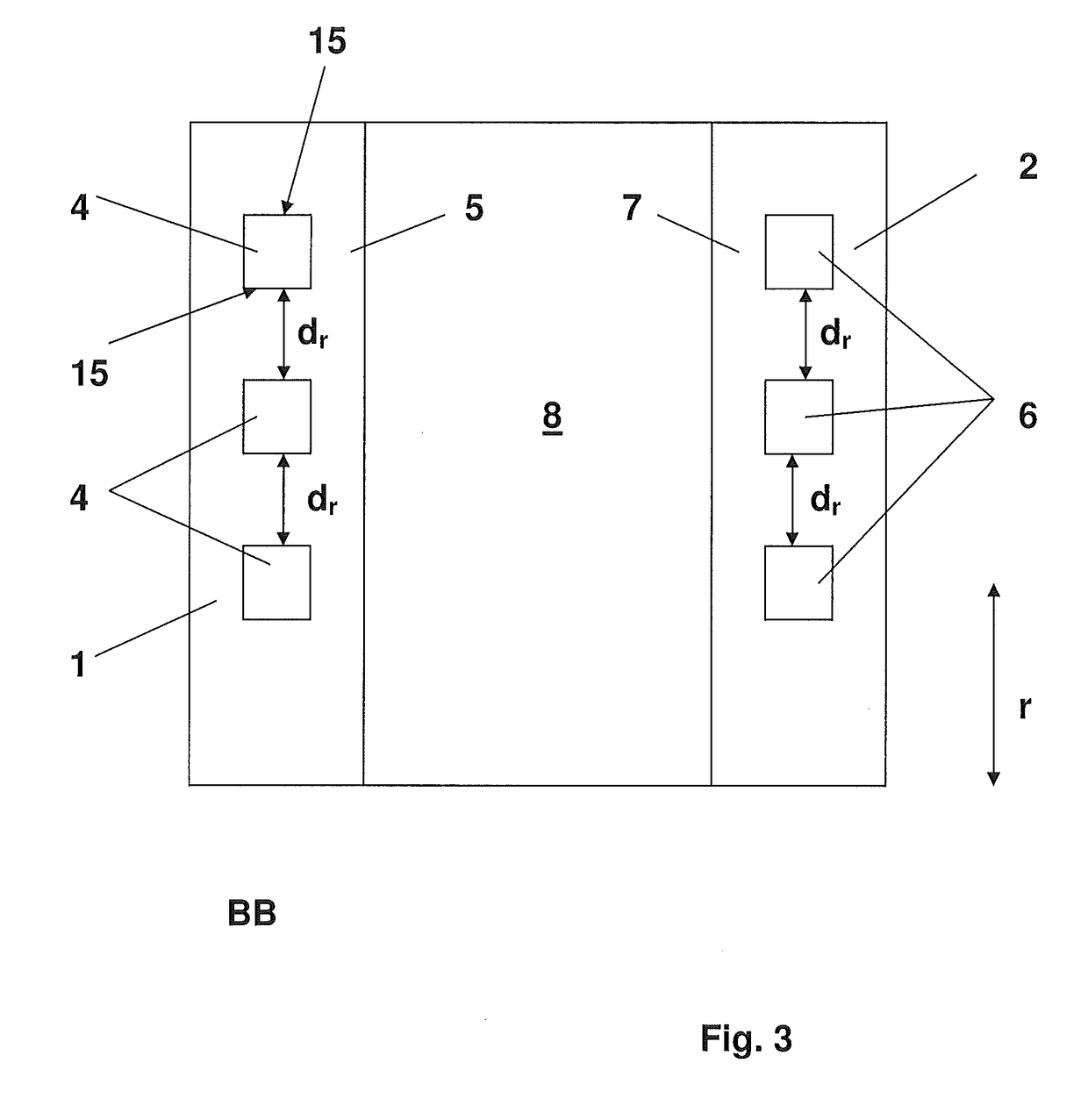
[0025]FIG. 1 shows a schematically section image of the trailing edge region 3 of an airfoil which provides a suction side wall 1 and a pressure side wall 2 extending in an axial direction A, which means from a leading edge which is not shown to the trailing edge 16. The suction wall 1 borders together with a first inner wall 5 a so called suction wall sided cooling channel 4, and further the pressure side wall 2 borders together with the second inner wall 7 the so called pressure wall sided cooling channel 6, both cooling channels 4, 6 merge together in a common channel region 12.

[0026]The first and second inner walls 5, 7 border a feed chamber 8 which is filled with compressed air which enters the suction and the pressure wall sided cooling channels 4, 6 by through holes 9, 10 (at least one through hole per wall is illustrated representing a multitude of such through holes). The common channel region 12 joins a discharge channel 11 which opens to the pressure side at the trailing ...


PUM


Abstract

An internally cooled airfoil for a rotary machine, for example, a gas turbine engine includes a suction and pressure side wall each extending in an axial direction, i.e. from a leading to a trailing edge of the airfoil. A suction wall sided cooling channel and a pressure wall sided cooling channel extend in the axial direction. A feed chamber is defined between a first and second inner wall for feeding the suction wall and pressure wall sided cooling channel each by at least one through hole inside of the first and second inner wall. The suction wall sided cooling channel and the pressure wall sided cooling channel extend into the trailing edge region separately. The suction wall sided cooling channel and the pressure wall sided cooling channel join before discharging at the trailing edge.

Description

CROSS-REFERENCE TO RELATED APPLICATIONS[0001]This application claims priority to PCT / EP2013 / 067227 filed Aug. 19, 2013, which claims priority to European application 12180953.7 filed Aug. 20, 2012, both of which are hereby incorporated in their entireties.TECHNICAL FIELD[0002]The present invention relates to an internally cooled airfoil for a rotary machine, preferably a gas turbine engine. Such airfoils, regardless of whether they are used as a vane or blade, typically comprise a suction side wall and a pressure side wall each extending in an axial direction, i.e. from a leading to a trailing edge region of said airfoil. Among the known airfoils those airfoils are of interest which have at least one suction wall sided cooling channel, extending in axial direction confined by the suction side wall and a first inner wall, and at least one pressure wall sided cooling channel, extending in axial direction confined by the pressure side wall and a second inner wall. Further at least one ...

Claims


Application Information

Patent Timeline
Patent Type & Authority Patents(United States)
IPC IPC(8): B22C9/24F01D9/02F01D5/18
CPCF01D5/189B22C9/24F01D9/02F01D5/186F05D2260/202F05D2260/201
Inventor KRUECKELS, JOERGWARDLE, BRIAN KENNETHBRANDL, HERBERTWIDMER, MARC
Owner ANSALDO ENERGIA IP UK LTD
Why Eureka
Try Eureka