

Sintering device for large-size optical fiber loosing powder rod and method
A sintering device and large-scale technology, applied in glass manufacturing equipment, manufacturing tools, etc., can solve the problems of unmentioned gas concentration distribution and full utilization, and achieve the goal of reducing the content of OH ions, reducing resource consumption, and enhancing the degree of turbulence Effect
- Summary
- Abstract
- Description
- Claims
- Application Information
AI Technical Summary
Problems solved by technology
Method used
Image

Examples
Embodiment 1
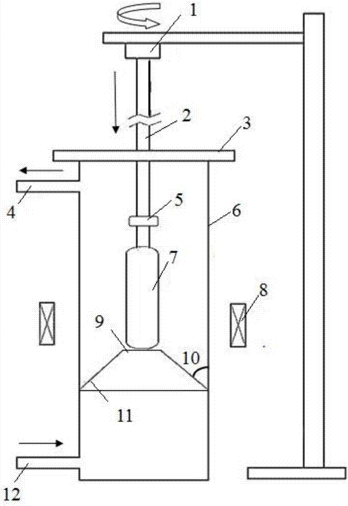
[0034]The loose powder rod 7 is clamped at the lower end of the quartz push rod 2, and the loose powder rod 7 is sent to the upper part of the sintering furnace core tube 6 through the rod feeding device 1; after the loose powder rod 7 is in place, the cover plate 3 on the top of the sintering furnace core tube 6 Also cover at the same time; Utilize induction heating furnace 8 to increase the temperature in the furnace core tube to 1000 ° C, and pass into process gases such as chlorine and helium of a specified amount through the air inlet 12 in the furnace core tube, the flow rate of chlorine is 0.05slm, helium The flow rate of the gas is 5slm, and the rod feeding device 1 is opened to send the loose powder rod 7 downward at a speed of 10mm / min, and rotate through the heating furnace 8 hot zones at a speed of 1rpm. After completing the dehydration program of the entire loose powder rod 7, The rod body stops at the position where the dehydration ends (at this time, the distance...
Embodiment 2
[0036] The loose powder rod 7 is clamped at the lower end of the quartz push rod 2, and the loose powder rod 7 is sent to the upper part of the sintering furnace core tube 6 through the rod feeding device 1; after the loose powder rod 7 is in place, the cover plate 3 on the top of the sintering furnace core tube 6 Also cover at the same time; Utilize induction heating furnace 8 to increase the temperature in the furnace core tube to 1200 ° C, and pass into process gases such as chlorine and helium of a specified amount through the air inlet 12 in the furnace core tube 6, the flow rate of chlorine is 1slm, , the flow rate of helium is 10slm, and the rod feeding device 1 is opened to send the loose powder rod 4 downward at a speed of 15mm / min, and rotate through the heating furnace 8 hot zones at a speed of 3rpm, when the dehydration program of the entire loose powder rod 7 is completed Finally, the rod body stops at the position where the dehydration ends (at this time, the dist...
Embodiment 3
[0038] The loose powder rod 7 is clamped at the lower end of the quartz push rod 2, and the loose powder rod 7 is sent to the upper part of the sintering furnace core tube 6 through the rod feeding device 1; after the loose powder rod 7 is in place, the cover plate on the top of the sintering furnace core tube 6 is also Cover simultaneously; Utilize the induction heating furnace 8 to increase the temperature in the core tube to 1300°C, and pass into process gases such as chlorine and helium of a specified amount through the air inlet 12 in the core tube 6, the flow rate of chlorine is 2slm, The flow rate of helium is 20slm, and the rod feeding device 1 is opened to send the loose powder rod 7 downward at a speed of 20mm / min, and rotate through the hot zone of the heating furnace at a speed of 5rpm. After the dehydration procedure of the entire loose powder rod 7 is completed, The rod body stops at the position where the dehydration ends (at this moment, the distance between the...
PUM
 Abstract
Description
Claims
Application Information