Heat management device of cold-heat-electricity supply system based on gas IC engine

A technology of combined cooling, heating, power, and gas-fired internal combustion engine, which is applied to the cooling of engines, internal combustion piston engines, and indirect heat exchangers. volume effect

Inactive Publication Date: 2007-06-13
SHANGHAI JIAO TONG UNIV
View PDF4 Cites 0 Cited by
  • Summary
  • Abstract
  • Description
  • Claims
  • Application Information

AI Technical Summary

Problems solved by technology

Relevant patent materials involving such proble

Method used


Image

  • Heat management device of cold-heat-electricity supply system based on gas IC engine

Examples


Embodiment Construction

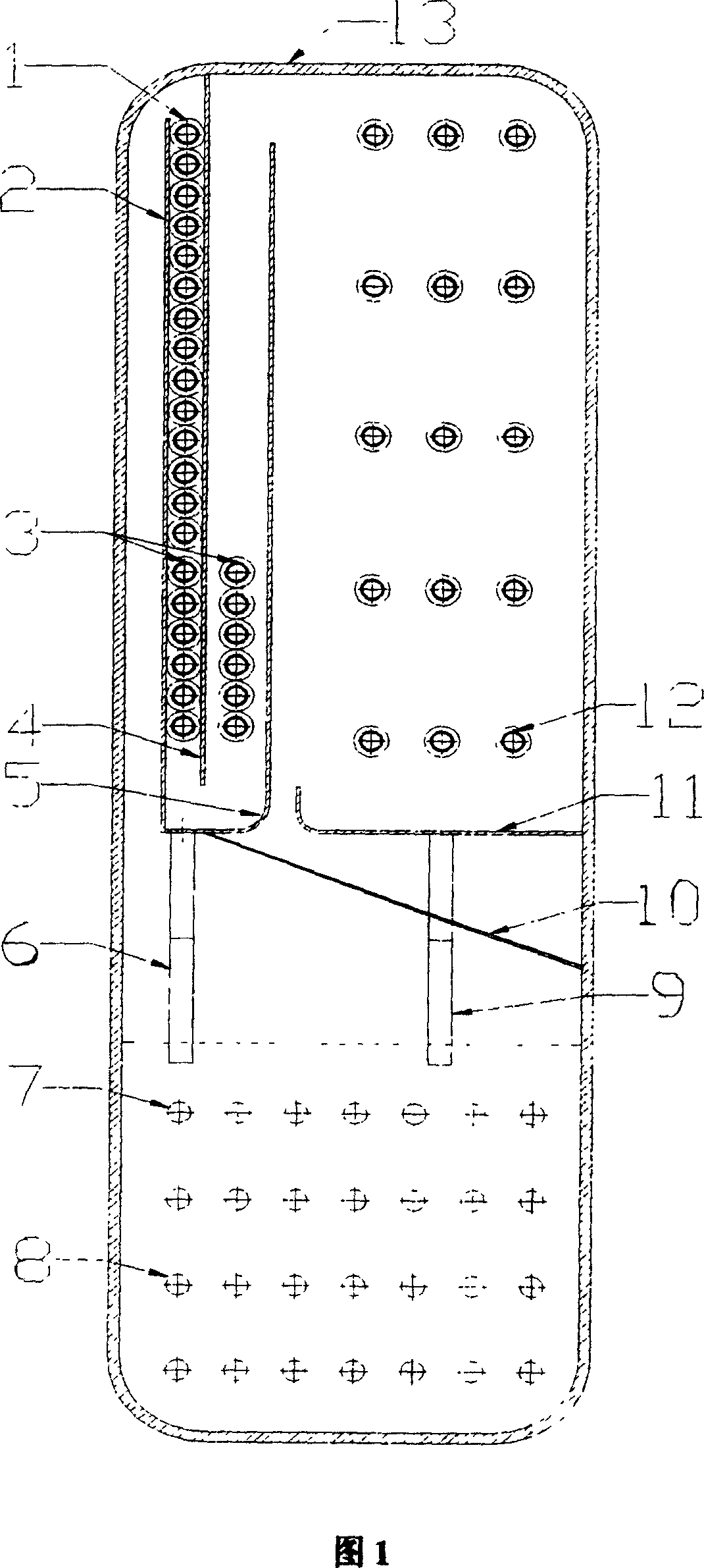
[0015] The technical solution of the present invention will be further described in detail below in conjunction with the accompanying drawings.

[0016] As shown in Figure 1, the thermal manager of the present invention includes: heat transfer tube 1 in the heat section, left air flow guide plate 2, heat transfer tube 3 in the heat dissipation section, right air flow guide plate 4, baffle plate 5, condensate seal 6. Engine jacket water heat transfer pipe 7, flue gas heat transfer pipe 8, air storage chamber liquid seal 9, airflow inclined guide plate 10, tray 11, air storage chamber condensation pipe 12, outer cover 13. The specific connection method of each component is as follows: the engine jacket water heat transfer tube 7 and the flue gas heat transfer tube 8 are arranged at the lower part of the heat manager and immersed in the working fluid. On the upper left side of the thermal manager, the left airflow guide plate 2, the right airflow guide plate 4 and the baffle plat...


PUM


Abstract

A heat supervisor of cooling , heating and electricity linkage system for gas combustion engine features arranging smoke heat transfer tube and water heat transfer tube of engine cylinder packing in working media liquid below supervisor ; using heat transfer tubes of heat use section and radiation section , gas flow leading plate , gas flow tilt leading plates and casing to form condensing channel for leading steam of working media downwards and channel for leading said steam upwards ; using baffle , casing and gas flow leading plate to enclose a gas storage chamber with condensing tube in it and elongating their liquid seals into working media liquid .

Description

technical field [0001] The invention relates to a heat manager of a combined cooling, heating and power supply system based on a gas internal combustion engine, which is a heat exchange device with functions of heat source temperature control, efficient heat transfer and automatic adjustment of heat output, and belongs to a new type of energy heat transfer technology field. Background technique [0002] With the implementation of the sustainable development strategy and the increasing awareness of energy saving and environmental protection, the combined cooling, heating and power system fueled by natural gas has gradually become an effective means to optimize the urban energy structure and improve the environmental quality. The combined cooling, heating and power system is based on the concept of energy cascade utilization, integrating refrigeration, heating (heating and hot water supply) and power generation, and its primary energy utilization rate can reach more than 80%. ...

Claims


Application Information

Patent Timeline
IPC IPC(8): F28D15/00F01P3/02F01N5/02
CPCY02T10/16Y02T10/12
Inventor 皇甫艺夏再忠吴静怡王如竹
Owner SHANGHAI JIAO TONG UNIV
Why Eureka
Try Eureka