
Mixing drum speed monitoring method and equipment and mixing truck

A speed monitoring and mixing drum technology, which is applied to cement mixing devices, chemical instruments and methods, control devices, etc., can solve the problems of inaccurate monitoring results of mixing drums and high monitoring costs

Active Publication Date: 2016-06-08
ZOOMLION HEAVY IND CO LTD
View PDF7 Cites 10 Cited by
  • Summary
  • Abstract
  • Description
  • Claims
  • Application Information

AI Technical Summary

Problems solved by technology

[0006] The embodiment of the present invention provides a mixing drum speed monitoring method, equipment and a mixer truck, which are used to solve the current problems of inaccurate monitoring results of the mixing drum and high monitoring costs.

Method used


Image

  • Mixing drum speed monitoring method and equipment and mixing truck
  • Mixing drum speed monitoring method and equipment and mixing truck

Examples


Embodiment 1

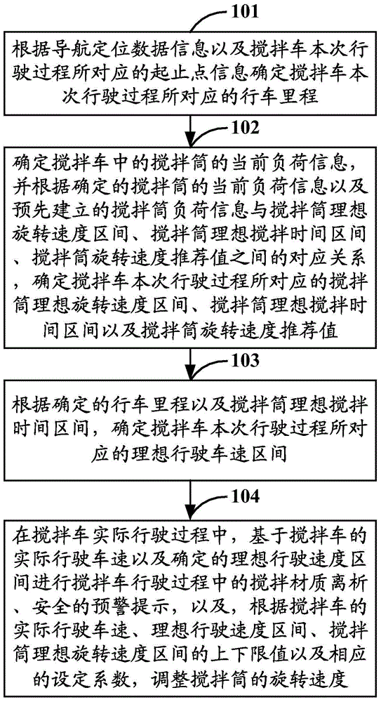
[0027] Embodiment 1 of the present invention provides a method for monitoring the speed of a mixing drum, such as figure 1 As shown, it is a schematic flow chart of the mixing drum speed monitoring method described in Embodiment 1 of the present invention, and the mixing drum speed monitoring method may specifically include the following steps:

[0028] Step 101: Determine the mileage corresponding to the current driving process of the mixer truck according to the navigation positioning data information and the corresponding start and end point information of the current driving process of the mixer truck.

[0029] Optionally, the navigation and positioning data information may be navigation and positioning data information based on GPS (Global Positioning System, Global Positioning System), or may also be navigation and positioning data information based on Beidou satellite navigation system, which is not made in the embodiment of the present invention. Any restrictions.

[...

Embodiment 2

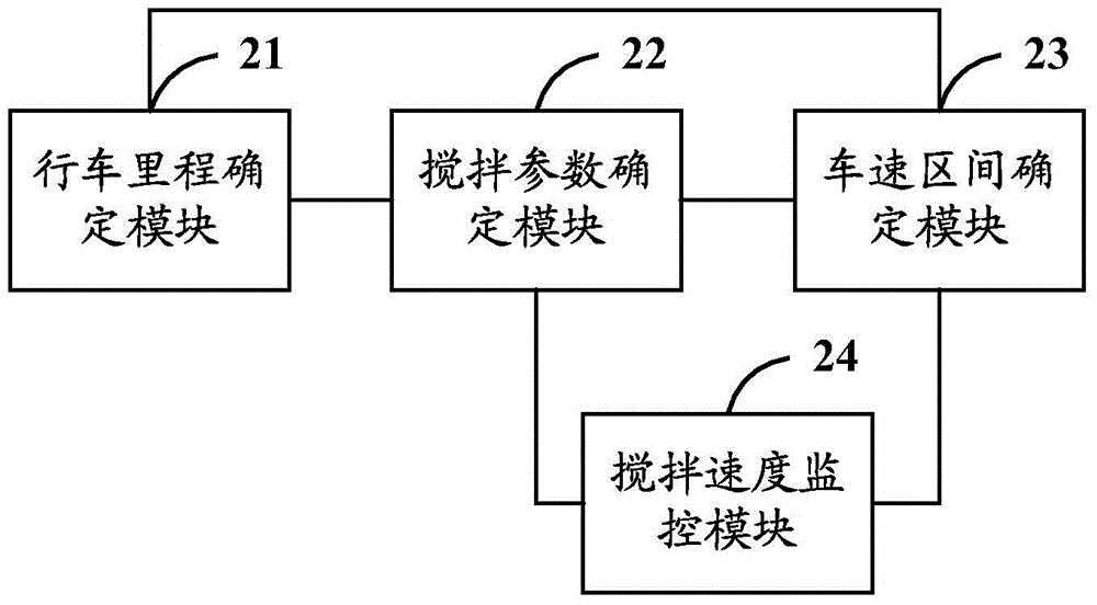
[0062] Embodiment 2 of the present invention provides a mixing drum speed monitoring device, such as figure 2 As shown, it is a schematic structural diagram of the mixing drum speed monitoring device described in Embodiment 2 of the present invention. The mixing drum speed monitoring device may specifically include a driving mileage determination module 21, a stirring parameter determination module 22, a vehicle speed range determination module 23 and Stirring speed monitoring module 24, wherein:

[0063] The mileage determination module 21 can be used to determine the mileage corresponding to the current driving process of the mixer truck according to the navigation positioning data information and the start and end point information corresponding to the current driving process of the mixer truck; wherein, the navigation positioning data information can be Navigation and positioning data information based on GPS, or, navigation and positioning data information based on Beido...


PUM


Abstract

The invention discloses a mixing drum speed monitoring method and equipment and a mixing truck. According to the scheme, mileage of the mixing truck can be determined through navigational positioning data, and an ideal rotation speed section, an ideal mixing time section of a mixing drum and the like can be obtained based on the current load of the mixing drum; an ideal running speed section of the mixing truck can be determined according to the determined mileage and the ideal mixing time section, and mixed material separation and safety warning reminding in the running process can be conducted based on the actual running speed of the mixing truck and the determined ideal running speed section; and the rotation speed of the mixing drum can be adjusted according to the actual running speed and the ideal running speed section of the mixing truck, and an upper limit value, a lower limit value and a set coefficient of the ideal rotation speed section of the mixing drum, so that the effects that the quality of mixed materials is controllable and potential safety hazards in the running process are reduced are achieved on the premise that the monitorability of control over the mixing drum in the running process of the mixing truck is effectively improved on the basis of reducing the monitoring cost.

Description

technical field [0001] The invention relates to the technical field of monitoring the mixing condition of a concrete mixer truck, in particular to a method and equipment for monitoring the speed of a mixing drum and a mixer truck. Background technique [0002] Usually, construction sites are widely required to use commercial concrete for construction operations. The concrete materials are prepared in advance by the concrete mixing plant and then loaded into the mixing drum of the mixer truck to be transported to the corresponding construction site according to the set standard. The set standard It is usually formulated by the industry according to the characteristics of the building materials in the country, such as the maximum allowable mixing time of the mixing drum from loading, conveying to unloading, and / or the maximum allowable rotation speed of the mixing drum, etc. [0003] Specifically, in order to ensure the quality of the concrete during transportation, so that th...

Claims


Application Information

Patent Timeline
IPC IPC(8): B28C5/42B28C7/02
Inventor 唐志杰万梁王佳茜陈祺吴亮
Owner ZOOMLION HEAVY IND CO LTD
Learn More