
Electroplating device and continuous vertical electroplating production line

A technology of electroplating device and electroplating tank, which is applied in the direction of electrolysis process, electrolysis components, charge manipulation, etc., to achieve the effect of simplifying the operation process

Active Publication Date: 2016-06-08
KUNSHAN DONGWEI MACHINERY CO LTD
View PDF8 Cites 13 Cited by
  • Summary
  • Abstract
  • Description
  • Claims
  • Application Information

AI Technical Summary

Problems solved by technology

[0005] The technical problem to be solved by the present invention is that the vertical electroplating substrate of the circuit board in the prior art cannot maintain the same height when moving in the electroplating tank.

Method used


Image

  • Electroplating device and continuous vertical electroplating production line
  • Electroplating device and continuous vertical electroplating production line
  • Electroplating device and continuous vertical electroplating production line

Examples


Embodiment 1

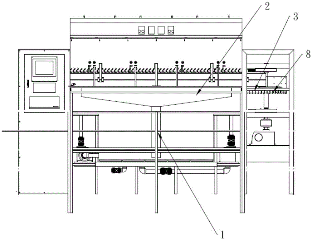
[0081] Such as figure 1 Shown, the present embodiment provides an electroplating device, comprising

[0082] Rack 1;

[0083] The electroplating tank 2 is arranged on the frame 1 and has an inlet and an outlet for the input and output of the substrate;

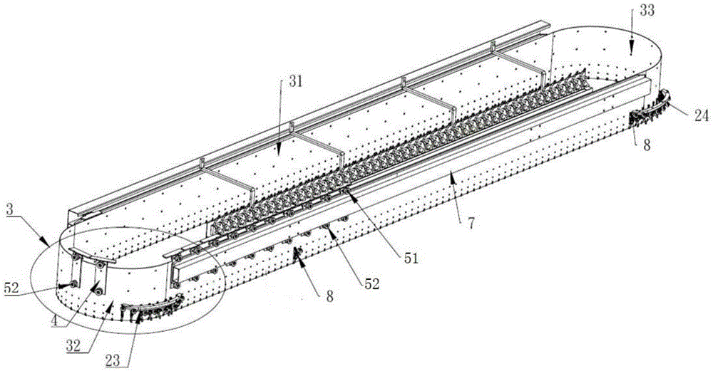
[0084] The conveyor belt 3 is arranged in the electroplating tank 2, and is used to drive the substrate fixed on the bottom thereof to move horizontally in the electroplating tank 2;

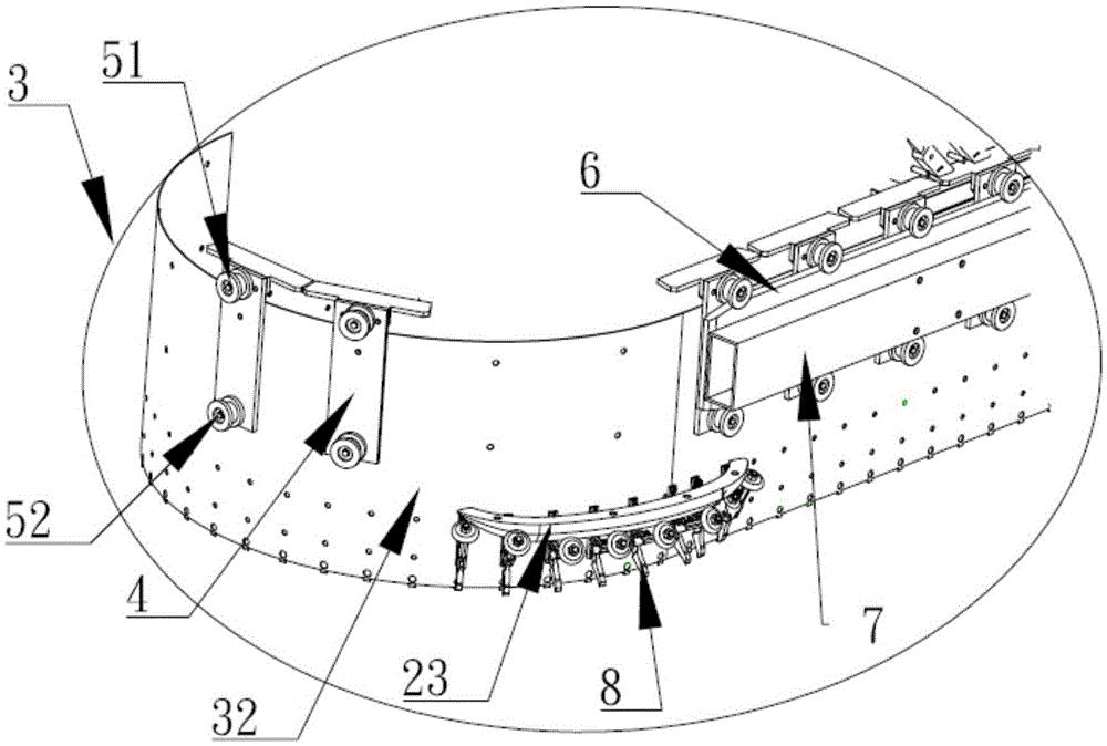
[0085] The limit mechanism is arranged on the frame 1 and is used to limit the downward movement of the conveyor belt 3 when the conveyor belt 3 moves.

[0086] In the electroplating device with the above-mentioned structure, during the moving process of the conveyor belt 3, the limit mechanism can limit the downward movement of the conveyor belt 3, so that the conveyor belt 3 keeps running at the same height in the electroplating tank 2, so that the bottom edge of the conveyor belt 3 can be fixed. The substrates run at the same height to ens...

Embodiment 2

[0135] This embodiment provides a continuous vertical electroplating production line, comprising

[0136] Continuous feeding system for continuous output of substrates;

[0137] The electroplating device is used for electroplating the substrate input into the electroplating tank 2 by the continuous feeding system;

[0138] The continuous receiving system is used to continuously collect the substrates output in the electroplating tank 2 into rolls;

[0139] The above-mentioned electroplating device is any one of the electroplating devices described in Embodiment 1.

[0140] This vertical electroplating production line adopts any one of the electroplating devices described in Embodiment 1, so that the conveyor belt 3 runs at the same height all the time in the electroplating tank 2, and ensures that the substrates fixed on the bottom edge of the conveyor belt 3 run at the same height, so that the substrates can be operated at the same height during electroplating. The tank 2 i...


PUM


Abstract

The invention discloses an electroplating device and a continuous vertical electroplating production line. The electroplating device comprises a rack, an electroplating bath arranged on the rack, a conveying belt arranged in the electroplating bath, a drive mechanism for driving the conveying belt to drive a substrate fixed to the bottom of the conveying belt to move in the electroplating bath and a limiting mechanism arranged on the rack. The continuous vertical electroplating production line comprises a continuous feeding system, the electroplating device and a continuous collecting system. In the moving process of the conveying belt, downward movement of the conveying belt can be limited by the limiting mechanism, so that the conveying belt is kept running at the same height in the electroplating bath all the time, then the substrate fixed to the edge of the bottom of the conveying belt runs at the same height, it is ensured that the substrate is evenly electroplated in the electroplating bath, and the electroplating performance of the electroplating device is improved.

Description

technical field [0001] The invention relates to the technical field of vertical electroplating of circuit boards, in particular to an electroplating device and a continuous vertical electroplating production line. Background technique [0002] In the prior art vertical electroplating production line for plates such as PCB boards, the substrate is conveyed into the electroplating tank through the feeding system, and the conveying device installed in the electroplating tank drives the substrate to move forward continuously in the horizontal direction. After the substrate is electroplated, the substrate Then it is output to the receiving system through the outlet of the electroplating device. [0003] At present, the conveying device installed in the electroplating tank mainly includes a driving wheel, a driven wheel and a conveyor belt. The conveyor belt is wound between the driving wheel and the driven wheel in the horizontal direction, and the top edge of the substrate enter...

Claims


Application Information

Patent Timeline
IPC IPC(8): C25D19/00B65G49/02
CPCB65G49/02C25D17/00
Inventor 张振李建中尚庆雷
Owner KUNSHAN DONGWEI MACHINERY CO LTD
Learn More