
Combined type brush sealing structure with radially adjustable brush wire bundle

A brush-type sealing and combined technology, which is applied in the direction of leakage prevention, engine components, machines/engines, etc., can solve the problems of insufficient closing of the gap between brush filament bundles, friction between brush filament bundles and rotors, increased leakage, etc., to achieve Reduce the straight-through effect, reduce the axial airflow pressure, and increase the effect of flow resistance

Active Publication Date: 2016-06-08
SHENYANG AEROSPACE UNIVERSITY
View PDF6 Cites 11 Cited by
  • Summary
  • Abstract
  • Description
  • Claims
  • Application Information

AI Technical Summary

Problems solved by technology

[0005] However, the interference assembly of traditional brush seals and the "pressure closure effect" of brush filaments will also cause problems such as rubbing between brush filament bundles and rotors.
In the case of brush seal brush filaments rubbing for a long time, the interference fit and "pressure closure effect" are not enough to close the large gap between the brush filament bundle and the rotor, and the increase in the gap between the brush filament bundle and the rotor will Causes increased leakage, leading to seal failure

Method used


Image

  • Combined type brush sealing structure with radially adjustable brush wire bundle
  • Combined type brush sealing structure with radially adjustable brush wire bundle
  • Combined type brush sealing structure with radially adjustable brush wire bundle

Examples


Embodiment Construction

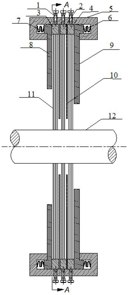
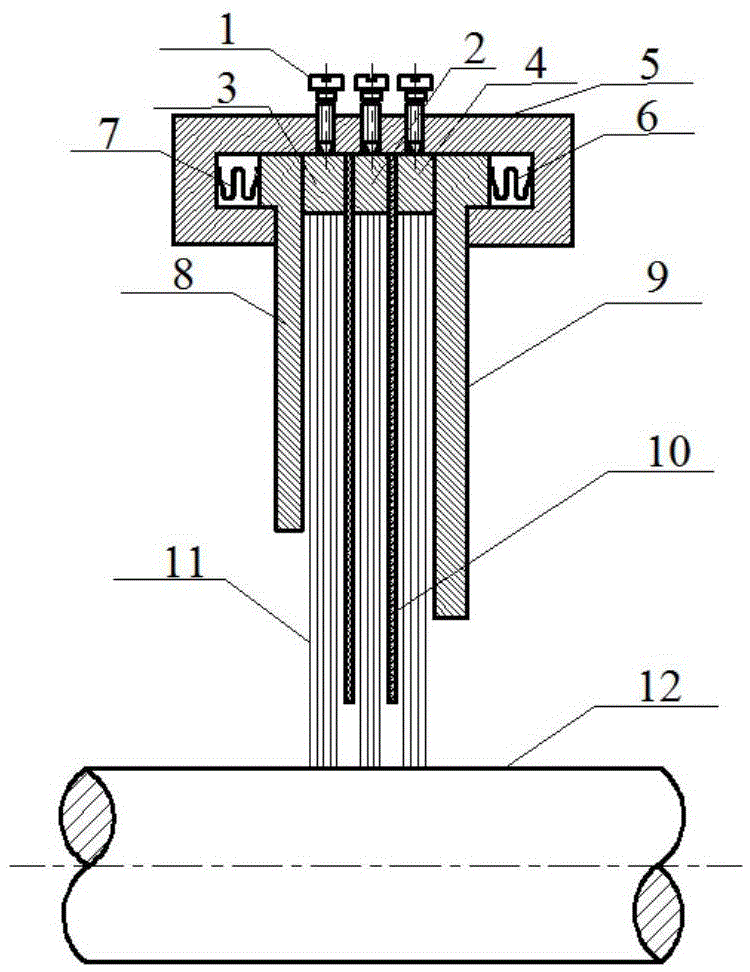
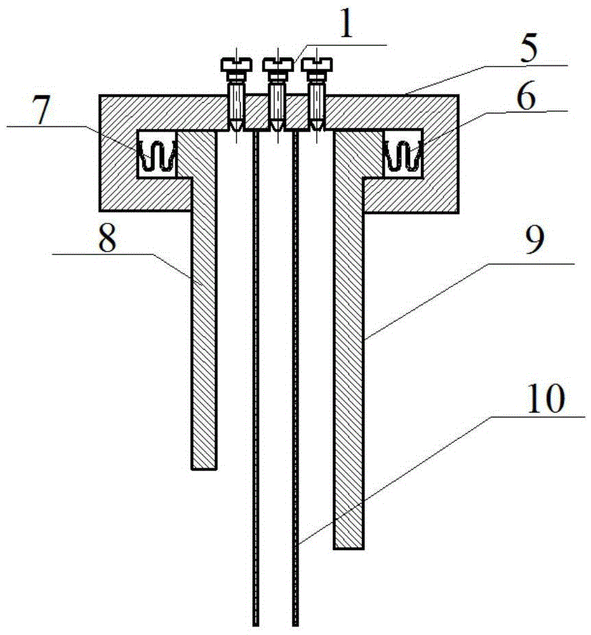
[0023] Such as Figure 1-Figure 7 Shown: a combined brush seal structure with radially adjustable brush bundles, including fastening screw 1, midstream brush ring 2, upstream brush ring 3, downstream brush ring 4, stator case 5, W Type sealing ring 6,7, front baffle 8, rear baffle 9, bearing plate 10, brush wire 11 and rotor 12. The middle brush wire ring 2 , the upstream brush wire ring 3 and the downstream brush wire ring 4 are fixed on the annular plate by the roots of the brush wire 11 through welding process, forming three brush wire rings 2 , 3 , 4 in the upper, middle and lower reaches. The brush wire ring is divided into 3 to 9 segments in the circumferential direction, and a gap of 1 mm to 3 mm is maintained between adjacent segments of the wire brush ring, and 1 to 3 fastening screws are set on the stator case corresponding to each segment of the wire brush ring 1, in order to adjust the radial gap between the brush filament 11 and the rotor 12. The W-shaped seal r...


PUM


Abstract

The invention discloses a combined type brush sealing structure with a radially adjustable brush wire bundle. The sealing structure comprises the following components: a front baffle, a back baffle, brush wire rings, fastening screws, bearing plates, w-shaped sealing rings and a stator casing, wherein roots of brush wires are fixed on an annular plate through a fusion welding process, so that an upstream brush wire ring, a midstream brush wire ring and a downstream brush wire ring are formed; the brush wire rings are divided into a plurality of sector sections circumferentially; the w-shaped sealing rings are clamped through brush sealing components and the stator casing; the bearing plates are installed in the stator casing and located between two brush wire rings; the lower ends of the fastening screws are inserted into the stator casing and located at the fixed ends of the brush wire rings; the fixed ends of brush wires are located on the brush wire rings, and the free ends of the brush wires make contact with a rotor; and the fastening screws acts on the brush wire rings through the stator casing. According to the combined type brush sealing structure, on the premise that a brush seal is not disassembled, the radial clearance between the brush wires and the rotor can be adjusted; besides, disassembly, replacement and maintenance are facilitated; the sealing property of the brush seal can be improved remarkably, and the usage cost is reduced; and excellent economic benefit is achieved.

Description

technical field [0001] The invention relates to a dynamic sealing structure applied in a rotating machine, in particular to a combined brush sealing structure with radially adjustable brush bundles. Background technique [0002] Brush seals are key components of rotating machinery such as aero-engines, steam turbines, and compressors. Compared with the traditional labyrinth seal, the brush seal not only has better sealing characteristics, but also is a flexible contact dynamic sealing technology, which can adapt to the instantaneous radial deformation or eccentric movement of the rotor. In addition, the brush wire of the brush seal The flexible contact with the rotor shaft can improve the vibration characteristics of the rotor system and ensure the safety of the unit operation. Therefore, brush seals are widely used in rotating machinery in aerospace, electric power, petrochemical and other industries. [0003] The brush seal is composed of the front baffle, the rear baffle...

Claims


Application Information

Patent Timeline
Patent Type & Authority Applications(China)
IPC IPC(8): F01D11/00
CPCF01D11/00
Inventor 赵欢孙丹刘宁宁白伟钢
Owner SHENYANG AEROSPACE UNIVERSITY
Learn More