
Opposite-side double-output-shaft large-transmission-ratio speed reducer with self-locking function

A dual output shaft, ratio reducer technology, applied in the direction of transmission, belt/chain/gear, mechanical equipment, etc., can solve the problems of small transmission ratio range, single output, single input of reduction device, etc.

Inactive Publication Date: 2016-06-08
BEIJING UNIV OF TECH
View PDF5 Cites 6 Cited by
  • Summary
  • Abstract
  • Description
  • Claims
  • Application Information

AI Technical Summary

Problems solved by technology

[0002] At present, the reduction gears that have been widely used in production are mostly single-input and single-output structures, and the transmission ratio range is relatively small, which cannot well adapt to the development of modern industry.

Method used


Image

  • Opposite-side double-output-shaft large-transmission-ratio speed reducer with self-locking function
  • Opposite-side double-output-shaft large-transmission-ratio speed reducer with self-locking function
  • Opposite-side double-output-shaft large-transmission-ratio speed reducer with self-locking function

Examples


Embodiment approach 1

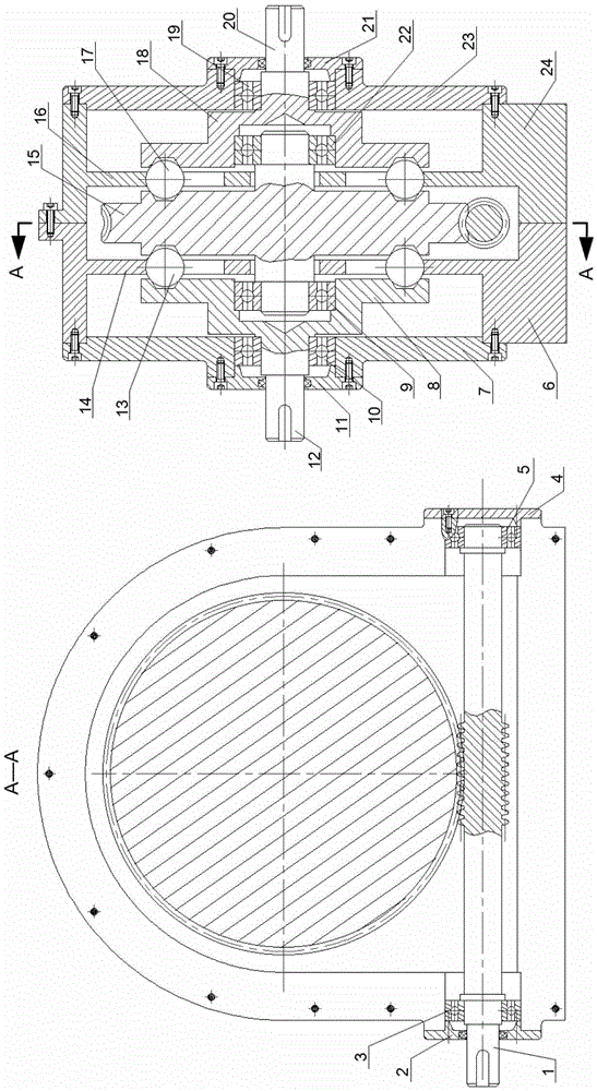
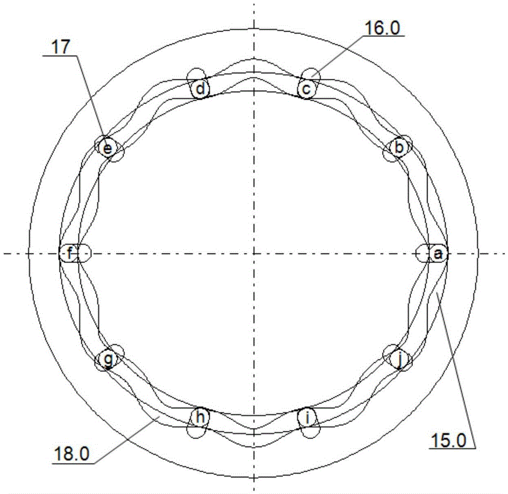
[0025] Such as figure 1 , Figure 2-1 to Figure 2-5 As shown, the speed reducer includes an input shaft 1, a multi-function disc 15, a left steel ball 13, a right steel ball 17, a left movable rack 14, a right movable rack 16, a left output disc 8, a right output disc 18, and a left output Shaft 12, right output shaft 20, left frame 6, right frame 24. The input shaft 1 and the multifunctional disk 15 transmit motion through tooth profile engagement; the frame is composed of a left frame 6 and a right frame 24, and the left movable gear frame 14 and the right movable gear frame 16 are fixedly connected to the left frame 6 and the right frame respectively. On the frame 24, the left steel balls 13 are evenly distributed in the radial grooves distributed along the circumferential direction on the left movable rack 14, and are always in the interlacing of the tooth profile grooves on the left end surface of the multi-function disk 15 and the tooth profile grooves of the left outpu...

Embodiment approach 2

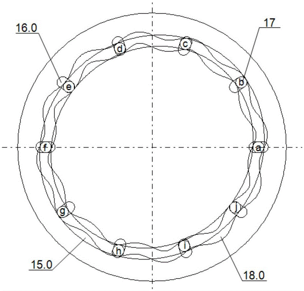
[0028] This embodiment is the same as Embodiment 1 in terms of the transmission principle of the movable tooth transmission mechanism, the difference lies in the transmission ratio i=-6 of the movable tooth transmission mechanism of Embodiment 2, that is, the direction of rotation of the multi-function disk and the right output disk is opposite. The tooth profile groove diagram of the component is as follows Figure 3-2 to Figure 3-4 shown.


PUM


Abstract

The invention provides an opposite-side double-output-shaft large-transmission-ratio speed reducer with a self-locking function and belongs to the technical field of mechanical transmission. The speed reducer comprises an input shaft, a multifunctional disc, left steel balls, right steel balls, a left movable tooth carrier, a right movable tooth carrier, a left output disc, a right output disc, a left output shaft, a right output shaft and a machine frame. Movement is transmitted between the input shaft and the multifunctional disc through tooth profile engagement. The machine frame is composed of a left machine frame body and a right machine frame body. The left movable tooth carrier and the right movable tooth carrier are fixedly connected to the left machine frame body and the right machine frame body correspondingly. The left steel balls are uniformly distributed in a radial groove which is distributed in the circumferential direction of the left movable tooth carrier and located in the staggered area between a tooth profile groove in the left end face of the multifunctional disc and the left output disc all the time. Similarly, the right steel balls are uniformly distributed in a radial groove which is distributed in the circumferential direction of the right movable tooth carrier and located in the staggered area between a tooth profile groove in the right end face of the multifunctional disc and the right output disc all the time. The left output disc and the right output disc are fixedly connected with the left output shaft and the right output shaft correspondingly. By the adoption of the speed reducer, single-shaft input and opposite-side double-shaft reduction output can be achieved, the rotation directions and reduction ratios of single-shaft input and opposite-side double-shaft reduction output are identical or different, and the speed reducer has the characteristics that the structure is compact, self-locking can be achieved, and the transmission ratio range is wide.

Description

technical field [0001] The patent of the present invention relates to a self-locking double output shaft large transmission ratio reducer, which belongs to the technical field of mechanical transmission. Background technique [0002] At present, the reduction gears that have been widely used in production are mostly single-input and single-output structures, and the range of transmission ratio is relatively small, which cannot well adapt to the development of modern industry. Therefore, in order to meet the needs of industrial production for reducers, a single-input, opposite-side double-output reducer with small size, compact structure, strong bearing capacity, wide range of reduction ratios, high transmission precision, and self-locking is designed. Contents of the invention [0003] The patent of the invention realizes the uniform speed input of one input shaft, and the simultaneous deceleration output of the two shafts on the opposite side. [0004] A self-locking lar...

Claims


Application Information

Patent Timeline
Patent Type & Authority Applications(China)
IPC IPC(8): F16H37/02
CPCF16H37/02
Inventor 李剑锋赵宏伟
Owner BEIJING UNIV OF TECH
Learn More