Eureka AIR delivers breakthrough ideas for toughest innovation challenges, trusted by R&D personnel around the world.

LED panel lamp and lamp bar installation structure thereof

A technology of LED light bar and installation structure, which is applied in the direction of lighting devices, fixed lighting devices, light guides of lighting devices, etc., which can solve problems such as inconvenience, affecting the overall strength of LED light bars, and difficulty in installation, so as to improve structural strength, easy operation and low cost. Time-saving and labor-saving, the effect of accurate and stable position

Active Publication Date: 2016-06-08
ANHUI ZERUN OPTOELECTRONICS
View PDF9 Cites 6 Cited by
  • Summary
  • Abstract
  • Description
  • Claims
  • Application Information

AI Technical Summary

Problems solved by technology

The patented structure realizes the positioning of the LED light bar and the light guide plate assembly by setting a positioning block on the LED light bar. The positioning holes set on the LED light bar affect the overall strength of the LED light bar, and the LED light bar of the LED panel light and The light guide plate assembly will produce some tight fit during installation, and the installation is difficult. After the assembly is completed, when replacing and maintaining the LED light bar, the entire frame needs to be disassembled, which is extremely inconvenient

Method used


Image

  • LED panel lamp and lamp bar installation structure thereof
  • LED panel lamp and lamp bar installation structure thereof
  • LED panel lamp and lamp bar installation structure thereof

Examples


Embodiment Construction

[0030] Embodiments of the present invention are described in detail below, examples of which are shown in the drawings, wherein the same or similar reference numerals designate the same or similar elements or elements having the same or similar functions throughout. The embodiments described below by referring to the figures are exemplary and are intended to explain the present invention and should not be construed as limiting the present invention.

[0031] In describing the present invention, it should be understood that the terms "center", "longitudinal", "transverse", "length", "width", "thickness", "upper", "lower", "front", " The orientations or positional relationships indicated by "rear", "left", "right", "vertical", "horizontal", "top", "bottom", "inner", "clockwise", "counterclockwise" are based on the attached The orientation or positional relationship shown in the figure is only for the convenience of describing the present invention and simplifying the description...


PUM


Abstract

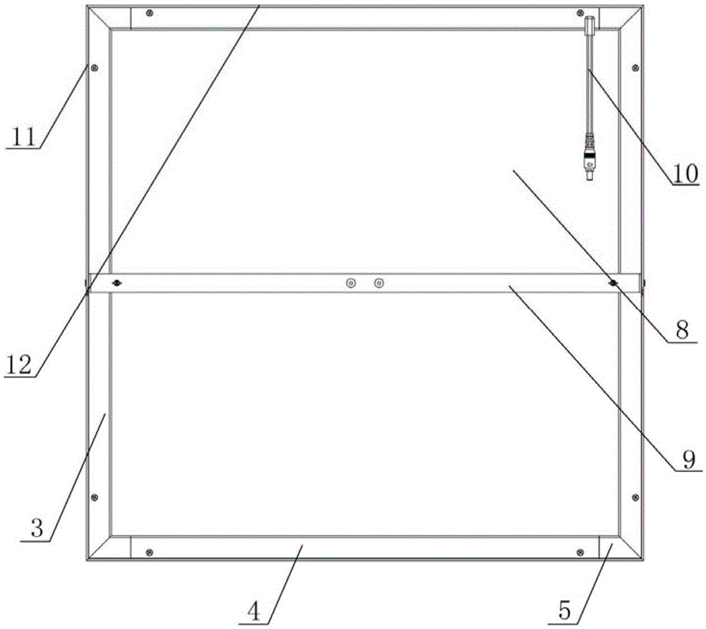
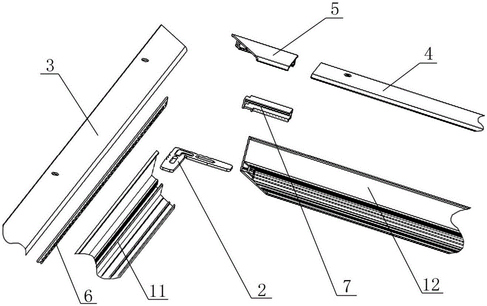
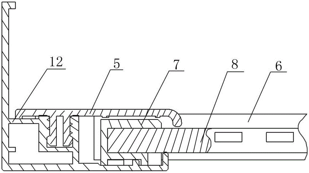
The invention belongs to the field of lighting lamps and particularly relates to a detachable LED panel lamp and a lamp bar installation structure thereof. The lamp bar installation structure comprises a frame, an LED lamp bar, positioning blocks and a light guide plate assembly, wherein the frame is formed by connection of two first frame profile bars and two second frame profile bars through four corner connection pieces, first profile bar cover plates are mounted on the first frame profile bars in a detachable connection manner, the middles of the first profile bar cover plates extend downwards to form positioning bars, the cross sections of the positioning bars of the first profile bar cover plates are in L shapes, the tail ends of the L shapes are folded to form second limit flanges, first limit flanges are further arranged in the positions, corresponding to the second limit flanges, of the first profile bar cover plates, the positioning bars of the first profile bar cover plates, the first limit flanges and the second limit flanges form an accommodating space, and the LED lamp bar is located in the accommodating space. The LED lamp bar is easy and convenient to replace and is time-saving and labor-saving.

Description

technical field [0001] The invention belongs to the field of lighting fixtures, in particular to a detachable LED panel light and a light bar installation structure thereof. Background technique [0002] Light-emitting diodes, as light-emitting devices, are more and more widely used in the field of lighting fixtures. LED has the advantages of low power consumption, high luminous intensity, energy saving and environmental protection. Compared with traditional lamps such as incandescent lamps and fluorescent lamps, LEDs are more and more preferred by users. In the field of home lighting, LED ceiling lamps have become more and more popular. [0003] In the prior art, the LED panel light using the light guide plate is provided with textures on one side of the light guide plate, such as silk screen texture, frosted texture or concave-convex texture, and a reflective layer is covered on the textured surface of the light guide plate, and then the surface of the light guide plate i...

Claims


Application Information

Patent Timeline
Patent Type & Authority Applications(China)
IPC IPC(8): F21S8/04F21V19/00F21V13/12F21V17/10F21V8/00F21Y115/10
CPCF21S8/04F21V13/12F21V17/10F21V19/001F21V2200/20
Inventor 石静张宏庭余密密
Owner ANHUI ZERUN OPTOELECTRONICS
Why Eureka
Eureka Blog
Learn More