Coordinate system measurement method for blade parts without positioning datum plane

A measurement method and coordinate system technology, applied in the field of measurement, can solve the problems of parts detection deviation and inability to measure

Active Publication Date: 2016-06-08
SHENYANG LIMING AERO-ENGINE GROUP CORPORATION
View PDF9 Cites 2 Cited by
  • Summary
  • Abstract
  • Description
  • Claims
  • Application Information

AI Technical Summary

Problems solved by technology

To solve the problems of detection deviation and unmeasurement of parts without direct positioning reference, apply MBD model definition technology and non-geometric feature fitting technology to automatically fit the part coordinate system through the measured 3D surface detection data, and then evaluate each measurement parameter

Method used


Image

  • Coordinate system measurement method for blade parts without positioning datum plane
  • Coordinate system measurement method for blade parts without positioning datum plane
  • Coordinate system measurement method for blade parts without positioning datum plane

Examples


Embodiment 1

[0026] The steps of measuring the coordinate system of blade parts without positioning reference plane are as follows:

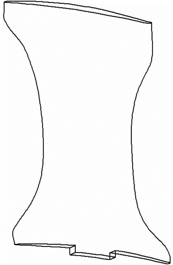
[0027] ① According to the coordinate data of the blade surface of the part, the MBD model of the part is generated by using the spline surface feature;

[0028] ②Import the MBD model into the offline measurement software, and adjust the direction of the coordinate system of the model to be consistent with the direction of the coordinate system of the measuring machine to avoid interference between the virtual probe and the model;

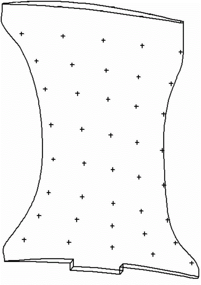
[0029] ③Design the distribution of measurement points: ensure that the measurement points cover the measured surface or the length of the part itself;

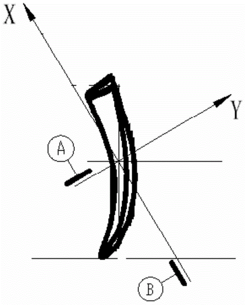
[0030] ④Create characteristic elements through the extracted measurement points: Create characteristic elements through the 3D fitting method. Using the 3D fitting method requires at least three measurement elements: (1) Fitting elements of measurement points on the leaf basin; (2...

Embodiment 2

[0038] The steps of the method for measuring the coordinate system of blade-like parts without a positioning reference plane are as follows:

[0039] ① According to the coordinate data of the blade surface, the MBD model of the part is generated by using the spline surface feature;

[0040] ②Import the MBD model into the offline measurement software, and adjust the direction of the coordinate system of the model to be consistent with the direction of the coordinate system of the measuring machine to avoid interference between the virtual probe and the model;

[0041] ③Design the distribution of measurement points: ensure that the measurement points cover the measured surface or the length of the part itself; use 8 rows and 10 columns of points to evenly distribute on the blade body, and evenly distribute the measurement points on the blade pot, blade back, leading edge, and trailing edge to avoid The coordinate fitting deviation caused by missing points in a certain area is un...


PUM


Abstract

Disclosed is a coordinate system measurement method for blade parts without a positioning datum plane. A measurement method for blades without direct positioning datum comprises the following steps: (1) generating an MBD model of a part based on spline surface characteristics according to blade profile coordinate data; (2) importing the MBD model into offline measurement software, and adjusting the coordinate system direction of the model to make the coordinate system direction of the model consistent with that of a measuring machine to avoid interference between a virtual probe and the model; and (3) designing measurement point distribution (please see attached figure 3) to ensure that the measurement points cover a measured surface or the part length. The method not only satisfies the requirements of parts, but also conforms to the principle of economical measurement. Through the measurement method for blades without direct positioning datum, measurement of special-form characteristics is realized. The method plays an important role in keeping the quality of engine running stable, improves the product quality and the detection efficiency, and is of great economic and social values.

Description

technical field [0001] The invention relates to the technical field of measurement methods, and in particular provides a method for measuring a coordinate system of blade parts without a positioning reference plane. Background technique [0002] There is a common non-direct positioning datum part in aero-engine. The characteristic of this kind of parts is that the positioning datum plane is too small, or the positioning datum plane cannot be measured. For parts with too small positioning datum, when the measured surface is far away from the positioning datum, the measurement result will deviate from the actual part. For parts with indirect positioning reference planes, machining datums are left in the general production process, and part inspection is only carried out during the processing process, while final parts are not inspected. [0003] Aeroengine stator blades ( figure 1 ) is a kind of indirect positioning reference surface type parts. When the part cuts off the p...

Claims


Application Information

Patent Timeline
Patent Type & Authority Applications(China)
IPC IPC(8): G01B21/00G06F17/50
Inventor 张露单纯利李景尧王东周永兆于绍永
Owner SHENYANG LIMING AERO-ENGINE GROUP CORPORATION
Why Eureka
Try Eureka