Analysis method for opening of laser blind hole

An analysis method and blind hole technology, applied in the direction of material analysis, material analysis, measurement device, etc. by optical means, can solve the problems of inaccurate positioning, inability to improve, and inability to guarantee the reliability of HDI products, so as to improve reliability. Effect

Active Publication Date: 2016-06-08
GUANGZHOU FASTPRINT CIRCUIT TECH +2
View PDF4 Cites 4 Cited by
  • Summary
  • Abstract
  • Description
  • Claims
  • Application Information

AI Technical Summary

Problems solved by technology

It is impossible to accurately locate the cause of the open circuit of the laser blind hole, so there is no way to improve it, and the reliability of HDI products cannot be guaranteed

Method used


Image

  • Analysis method for opening of laser blind hole

Examples


Embodiment Construction

[0017] Below, in conjunction with accompanying drawing and specific embodiment, the present invention is described further:

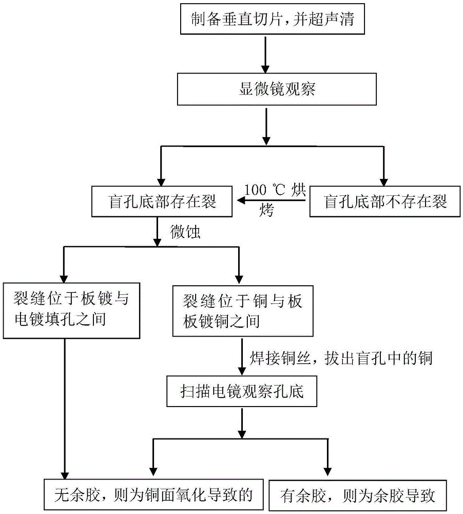
[0018] Such as figure 1 An analysis method for the open circuit of a laser blind hole is shown, comprising the following steps:

[0019] S1. Make vertical slices for laser blind holes with open circuit failure;

[0020] S2. Use a microscope to observe whether there are cracks at the bottom of the laser blind hole;

[0021] S3. If cracks are found by observation, use microetching solution to micro-etch the copper surface of the vertical slice, and observe the layer position where the crack is located;

[0022] S4. a. If the crack is located between the plate copper plating and the electroplating filled hole, and there is no glue at the bottom of the laser blind hole, it is judged that the laser blind hole is open due to the oxidation of the copper surface; b. If the crack is located between the base copper and the plate copper plating If there is no r...


PUM


Abstract

The invention discloses an analysis method for opening of a laser blind hole. The analysis method comprises the following steps: S1) preparing a vertical slice for the laser blind hole with invalid opening; S2) observing by a microscope if a crack exists at the bottom of the laser blind hole; S3) if a crack is detected, using a micro-etching fluid for micro-etching a copper surface of the vertical slice and observing the position of the layer on which the crack is located; S4): a) confirming as opening of the laser blind hole caused by the oxidation of the copper surface if the crack is located between plating copper and an electroplate filling hole and no residual glue exists at the bottom of the laser blind hole, and b) confirming as opening of the laser blind hole caused by the oxidation of the copper surface if the crack is located between base copper and the plating copper and no residual glue exists at the bottom of the laser blind hole, and confirming as opening of the laser blind hole caused by the residual glue if the residual glue exists at the bottom of the laser blind hole. According to the analysis method provided by the invention, the reason of opening of the laser blind hole can be accurately acquired, so that the opening problem of the laser blind hole can be solved.

Description

technical field [0001] The invention relates to an analysis method for the open circuit of a laser blind hole. Background technique [0002] High-density interconnect PCB (HDI) products realize the connection between any layers through laser blind holes, which provides favorable conditions for high-density wiring, high-frequency transmission, and multi-layering. The process of laser blind holes in the PCB manufacturing process is: laser drilling → plasma cleaning → copper sinking → plate plating → electroplating filling holes. There are more and more branches of laser blind holes in HDI. Therefore, the reliability of laser blind holes directly affects the quality of HDI products. However, open-circuit failures often occur in laser blind vias after HDI is heat-treated. [0003] The traditional open-circuit analysis method of laser blind holes is: simple micro-slice analysis of laser blind holes. Slice analysis can usually only observe cracks at the bottom of blind holes, an...

Claims


Application Information

Patent Timeline
Patent Type & Authority Applications(China)
IPC IPC(8): G01N21/956
CPCG01N21/956G01N2021/95638
Inventor 况东来胡梦海陈蓓
Owner GUANGZHOU FASTPRINT CIRCUIT TECH
Why Eureka
Try Eureka