Method for cutting liquid crystal display panel

A cutting method and liquid crystal panel technology, applied in glass cutting devices, optics, instruments, etc., can solve the problems of many process steps and low cutting efficiency

Inactive Publication Date: 2016-06-08
TCL CHINA STAR OPTOELECTRONICS TECH CO LTD
View PDF7 Cites 6 Cited by
  • Summary
  • Abstract
  • Description
  • Claims
  • Application Information

AI Technical Summary

Problems solved by technology

This leads to more process links and low cutting efficiency

Method used


Image

  • Method for cutting liquid crystal display panel
  • Method for cutting liquid crystal display panel
  • Method for cutting liquid crystal display panel

Examples


Embodiment Construction

[0022] The technical solutions in the embodiments of the present invention will be clearly and completely described below in conjunction with the accompanying drawings in the embodiments of the present invention. Obviously, the described embodiments are only a part of the embodiments of the present invention, rather than all the embodiments. Based on the embodiments of the present invention, all other embodiments obtained by those of ordinary skill in the art without creative work shall fall within the protection scope of the present invention.

[0023] The cutting device in this embodiment is a non-cross type (not shown) cutting machine. In other embodiments, other types of cutting machines can also be used.

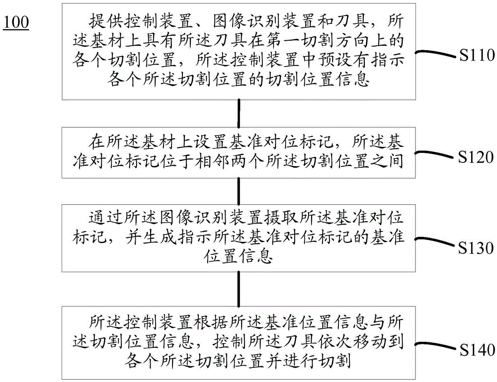
[0024] Such as figure 1 As shown, the method 100 for cutting a liquid crystal panel of this embodiment includes:

[0025] S110: Provide a control device, an image recognition device, and a cutter, the substrate has each cutting position of the cutter in a first cutting directi...


PUM


Abstract

The invention discloses a method for cutting a liquid crystal display panel. The method comprises the steps of providing a control device, an image recognition device and a tool, wherein a substrate is provided with all cutting positions, in a first cutting direction, of the tool, and cutting position information indicating all the cutting positions is preset in the control device; arranging reference alignment marks on the substrate, wherein the reference alignment marks are located between every two adjacent cutting positions; shooting the reference alignment marks through the image recognition device, and generating reference positional information indicating the reference alignment marks; controlling the tool to move to the cutting positions in sequence for cutting through the control device according to the reference positional information and the cutting position information. By means of the cutting method, the cutting process can be simplified, and cutting efficiency can be improved.

Description

Technical field [0001] The present invention relates to the technical field of liquid crystal panel manufacturing, in particular to a method for cutting a liquid crystal panel. Background technique [0002] In the manufacturing process of liquid crystal panels, it is necessary to cut the entire substrate to separate liquid crystal panels that meet the design size. Each liquid crystal panel to be formed on the substrate has an alignment mark. CCD (ChargeCoupled Device) recognizes the alignment mark and generates cutting control information, and the cutter cuts according to the cutting control information. The part cut by the knife is called waste. In the prior art, in the same cutting direction (for example, vertical or horizontal), after the tool completes a cut, the machine needs to forward the substrate to a position that can be scanned by the CCD, and then the CCD recognizes the second set of alignment again Mark to control the tool to continue the second cut. This leads to...

Claims


Application Information

Patent Timeline
Patent Type & Authority Applications(China)
IPC IPC(8): G02F1/13
CPCG02F1/133351G02F1/133354B26D5/007B26D7/2628C03B33/037C03B33/07G02F1/1303Y02P40/57G02F1/1333
Inventor 班松
Owner TCL CHINA STAR OPTOELECTRONICS TECH CO LTD
Why Eureka
Try Eureka