Unmanned gyroplane moving target autonomous tracking device and control method thereof

A technology of moving targets and autonomous tracking, which is applied in the direction of finding targets, etc., can solve the problems of reducing aircraft maneuverability, difficult real-time requirements, discontinuous flight process, etc., and achieve the effect of improving real-time and smoothness

Active Publication Date: 2016-06-08
SUN YAT SEN UNIV
View PDF5 Cites 50 Cited by
  • Summary
  • Abstract
  • Description
  • Claims
  • Application Information

AI Technical Summary

Problems solved by technology

In addition, the tracking and guidance of the aircraft seldom consider the inertial constraints of the aircraft itself, and the trajectory planning with a large amount of calculation is difficult to be directly used because of real-time requirements, so the current trajectory of the target position is usually directly used as the reference traj

Method used


Image

  • Unmanned gyroplane moving target autonomous tracking device and control method thereof
  • Unmanned gyroplane moving target autonomous tracking device and control method thereof
  • Unmanned gyroplane moving target autonomous tracking device and control method thereof

Examples


Embodiment Construction

[0027] The accompanying drawings are for illustrative purposes only, and should not be construed as limitations on this patent; in order to better illustrate this embodiment, certain components in the accompanying drawings will be omitted, enlarged or reduced, and do not represent the size of the actual product; for those skilled in the art It is understandable that some well-known structures and descriptions thereof may be omitted in the drawings. The positional relationship described in the drawings is for illustrative purposes only, and should not be construed as a limitation on this patent.

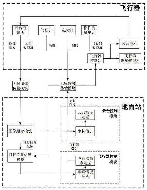
[0028] Such as figure 1 Shown, a kind of rotor unmanned aerial vehicle mobile target autonomous tracking device, wherein, comprise aircraft and ground station, described aircraft comprises aircraft controller, the aircraft propeller motor that is connected with aircraft controller, pan-tilt motor, described cloud The platform motor is connected to the PTZ camera;

[0029] A wireless...


PUM


Abstract

The invention relates to the technical field of unmanned gyroplane autonomous tracking, in particular to an unmanned gyroplane moving target autonomous tracking device based on a pan-tilt camera and an airborne sensor. The unmanned gyroplane moving target autonomous tracking device comprises an aircraft and a ground station. The aircraft comprises an aircraft controller, an aircraft propeller motor connected with the aircraft controller, and a pan-tilt motor. The pan-tilt motor is connected with the pan-tilt camera. A wireless image transmission module and a wireless data transmission module are arranged between the aircraft and the ground station. The aircraft and the ground station are connected through the wireless image transmission module and the wireless data transmission module. Images obtained by the airborne pan-tilt camera serve as input of a system, coordinates of a target in the images are obtained on the ground station through a Struck algorithm, modeling is conducted on the coordinates of the target through a uniformly accelerated motion (CA) model, the control quantity of a pan-tilt is designed according to the coordinates, estimated through modeling, of the target, and accordingly tracking instantaneity and smoothness of the pan-tilt camera are guaranteed.

Description

technical field [0001] The present invention relates to the technical field of autonomous tracking of rotor UAVs, and more specifically, to an autonomous tracking device for a moving target of a rotor UAV based on a pan-tilt camera and an onboard sensor. Background technique [0002] Compared with fixed-wing aircraft, quadrotor aircraft has the advantages of vertical take-off and landing, low-altitude hovering, and fast maneuvering steering, so it is widely used in military, agricultural, aerial photography and other fields. How to effectively identify, track and follow the targets collected by the camera is a hot issue in the field of aircraft research. The tracking of maneuvering targets is different from the tracking of stationary targets. The relative position of the target and the aircraft will not only change due to the movement of the aircraft, but also the movement of the target itself will produce a large relative distance change. This not only brings great difficu...

Claims


Application Information

Patent Timeline
IPC IPC(8): G05D1/12
CPCG05D1/12
Inventor 成慧关宇卫林倞
Owner SUN YAT SEN UNIV
Why Eureka
Try Eureka