Unit type heat source system of corn ear dryer

A corn cob and heat source system technology, applied in the direction of dry preservation of seeds, adaptation to climate change, etc., can solve the problems of energy waste, large footprint, high cost, etc., to avoid waste of waste heat, save floor space, and scientific layout Effect

Pending Publication Date: 2016-06-15
石河子市华农种子机械制造有限公司
View PDF8 Cites 1 Cited by
  • Summary
  • Abstract
  • Description
  • Claims
  • Application Information

AI Technical Summary

Problems solved by technology

[0002] At present, the corn ear drying system is composed of multiple single-room drying rooms built as a whole. The construction scale of the drying room is fixed, and it is difficult to expand the scale; in addition, it needs to be equipped with an independently built hot stove workshop, which burns bituminous coal powder. The heat generated requires multiple large fans, each fan has an air volume of 260,000 cubic meters, a wind pressure of 200-260mm water column, and each fan consumes 160kw of power. channel, and then rely on the pressure in the hot air channel to send the hot air into each drying room to dry the ears of corn. The whole system is expensive, occupies a large area, and consumes a lot of energy. There is a lot of energy waste.

Method used


Image

  • Unit type heat source system of corn ear dryer
  • Unit type heat source system of corn ear dryer
  • Unit type heat source system of corn ear dryer

Examples


Embodiment 1

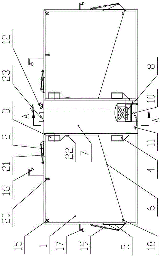
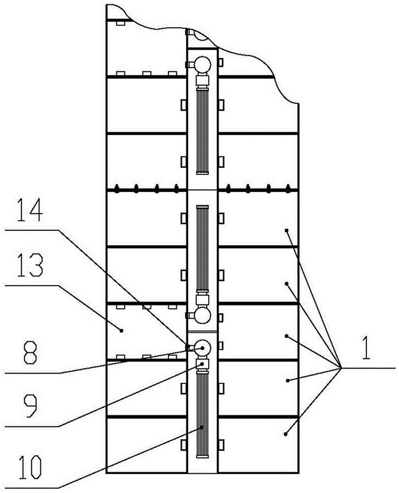
[0023] Example 1, such as figure 1 , 2 As shown, the heat source center is a heat source chamber 7, and the heat source chamber 7 is provided with a hot blast stove 8, a filter 9 and a heat exchanger 10 connected together in sequence; The blower fan 11 and the hot blast stove 8 are equipped with a suction fan 12 outside the heat source chamber 7 through a pipeline passing through the top of the heat source chamber 7 . The hot blast stove 8 can generate heat by burning coal, fuel oil, gas, biomass or by solar energy and electricity conversion, the filter 9 can reduce environmental pollution, and the heat exchanger 10 can accelerate heat exchange.

Embodiment 2

[0024] Example 2, such as figure 1 , 3 As shown, the center of the heat source is two heat source chambers 7 facing each other; each heat source chamber 7 is provided with a hot blast stove 8, a filter 9 and a heat exchanger 10 connected sequentially from the inside to the outside; the hot blast stove 8 A combustion-supporting fan 11 located in the corresponding heat source chamber 7 is installed on the top, and a suction fan 12 located outside the corresponding heat source chamber 7 is installed on the hot blast stove 8 through a pipeline passing through the top of the corresponding heat source chamber 7; the two rows of drying rooms are left and right Symmetrically distributed, each row of drying rooms is five adjacent and independent drying rooms 1 . When applying the present invention on a large scale and in a wide range, the combination of two heat source chambers 7 facing each other and five drying chambers 1 in each row has a compact structure and sufficient heat utili...


PUM


Abstract

The invention relates to a unit type heat source system of a corn ear dryer. The unit type heat source system comprises a left row of drying rooms, a right row of drying rooms, and an independent and sealed heat source center which is formed between the two rows of drying rooms, wherein the left row of drying room and the right row of drying rooms are arranged in a spaced manner; each row of the drying rooms comprises at least one independent drying chamber, and a feeding door capable of being opened and closed is arranged at the top part of each drying chamber; an upper circulating fan and a lower circulating fan which are communicated with the heat source center respectively are arranged on the side wall, close to the heat source center, of each drying chamber. Due to the implementation of the technical scheme, the unit type heat source system organically combines the drying chambers and the heat source center into a unit by the arrangement that the heat source center is formed between the two rows of drying rooms, and heat in the heat source center can be reasonably and uniformly provided for each drying chamber by the upper circulating fans and the lower circulating fans, therefore, the arrangement is scientific, and the occupied area is saved; heat generated by the heat source center directly enters the drying chambers without consumption halfway, so that waste of waste heat is avoided, and a large amount of energy consumed by use of high-power fans due to long-distance heat sending is saved.

Description

technical field [0001] The present application relates to the technical field of seed processing devices, in particular to a heat source system for a unitized corn cob dryer. Background technique [0002] At present, the corn ear drying system is composed of multiple single-room drying rooms built as a whole. The construction scale of the drying room is fixed, and it is difficult to expand the scale; in addition, it needs to be equipped with an independently built hot stove workshop, which burns bituminous coal powder. The heat generated requires multiple large fans, each fan has an air volume of 260,000 cubic meters, a wind pressure of 200-260mm water column, and each fan consumes 160kw of power. In the channel, the hot air is then sent into each drying chamber to dry the ears of corn by the pressure in the hot air channel. The whole system is expensive, occupies a large area, and consumes a lot of energy. There is a lot of energy waste. Contents of the invention [0003...

Claims


Application Information

Patent Timeline
Patent Type & Authority Applications(China)
IPC IPC(8): A23B9/08
CPCA23B9/08Y02A40/90
Inventor 马仁杰郭广马明銮陈强
Owner 石河子市华农种子机械制造有限公司
Why Eureka
Try Eureka