Ball-milling mechanical device

A mechanical device and ball milling technology, applied in the direction of grain processing, etc., can solve the problems of difficult to grasp the size of the crushing particle size, reduce the service life of the equipment, and difficult to control the airflow speed, and achieve the effect of simple structure, improved production efficiency, and improved service life.

Inactive Publication Date: 2016-06-15
TAICANG RONGZHONG ELECTRIC CO LTD
View PDF7 Cites 3 Cited by
  • Summary
  • Abstract
  • Description
  • Claims
  • Application Information

AI Technical Summary

Problems solved by technology

[0003] The ball mill is composed of the main parts such as the feeding part, the discharging part, the grinding part, the transmission part (reducer, motor), etc. The box is inlaid with a wear-resistant liner, which has good wear resistance, and the inner liner is removable. Its working principle is: select according to the particle size of the grinding material, and the material is loaded into the box by the feed shaft of the ball mill. When the ball mill is running, the ball is attached to the liner of the box due to inertia, centrifugal force and friction. It is taken away by the box, and when it is brought to a certain height, it is thrown down due to its own gravity. The falling ball crushes the material in the box like a projectile, and then it is discharged by the discharge plate, but It is difficult to control the airflow speed of the traditional ball mill mechanical device, which makes it difficult to grasp the size of the crushed particles, and the airflow contains moisture, which will cause certain corrosion to the machine body and reduce the service life of the equipment

Method used


Image

  • Ball-milling mechanical device

Examples


Embodiment Construction

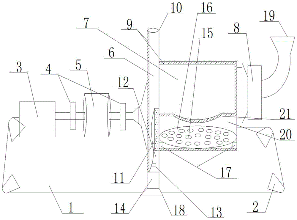
[0016] Such as figure 1 As shown, a ball mill mechanical device of the present invention includes a base 1, a motor 3, a reducer 5 and a box body 7, the four corners of the base 1 are respectively provided with legs 2, the motor 3 is fixed on the base 1, and the motor 3 is connected to One end of the reducer 5, the other end of the reducer 5 is fixedly connected to one side of the column 6, the other side of the column 6 is fixedly connected to the box body 7, the top of the column 6 is provided with a ventilation hole 10, and the connection between the column 6 and the box body 7 is provided with a discharge plate 11 , the discharge plate 11 is connected to the discharge chamber 12, the discharge chamber 12 is connected to the collecting cover 14, the connection between the column 6 and the discharge chamber 12 is provided with a material rejection hole 13, and the box body 7 is connected to the feed port through the air velocity control device 8 19. The lower half of the box...


PUM


Abstract

The invention discloses a ball mill mechanical device, which comprises a base, a motor, a reducer and a box body, four corners of the base are respectively provided with outriggers, the motor is fixed on the base, the motor is connected to one end of the reducer, and the other end of the reducer is fixedly connected to a column One side of the column and the other side of the column are fixedly connected to the box body. There is a vent hole at the top of the column. A discharge plate is set at the connection between the column and the box body. The discharge plate is connected to the discharge cavity, and the discharge cavity is connected to the collection cover. There is a material rejection hole at the connection of the cavity, and the box is connected to the feed port through the air velocity control device. At the same time, there is a water-absorbing layer and a heat-absorbing device in the box, which improves the service life of the equipment, and the airflow speed control device can flexibly control the airflow speed, which improves the production efficiency.

Description

technical field [0001] The invention relates to a ball mill mechanical device. Background technique [0002] The ball mill mechanical device is the key equipment for crushing the material after it is crushed. It is widely used in cement, silicate products, new building materials 52555, refractory materials, chemical fertilizers, black and non-ferrous metal beneficiation and glass ceramics and other production industries. Various ores and other grindable materials are used for dry or wet grinding. At the same time, ball mills are suitable for grinding various ores and other materials. They are widely used in mineral processing, building materials and chemical industries. They can be divided into dry and wet types. A grinding method. [0003] The ball mill is composed of the main parts such as the feeding part, the discharging part, the grinding part, the transmission part (reducer, motor), etc. The box is inlaid with a wear-resistant liner, which has good wear resistance, an...

Claims


Application Information

Patent Timeline
Patent Type & Authority Applications(China)
IPC IPC(8): B02C17/10B02C17/18B02C17/20B02C17/22B02C25/00
CPCB02C17/10B02C17/18B02C17/20B02C17/22B02C25/00
Inventor 符建豪
Owner TAICANG RONGZHONG ELECTRIC CO LTD
Why Eureka
Try Eureka