A turbulent flow electrolyzer and a turbulent flow electrolysis production system composed of turbulent flow electrolyzers

A production system and electrolysis system technology, which is applied in the electrolysis process, electrolysis components, photography process, etc., can solve the problems affecting electrolysis operations, different reaction conditions of electrolysis cells, deterioration of electrolysis cell conditions, etc., to improve electrolysis production efficiency, mechanical The operation method is feasible and the effect of reducing the power consumption of electrolysis

Active Publication Date: 2018-06-22
中锰(湖北)科技发展有限公司
View PDF9 Cites 0 Cited by
  • Summary
  • Abstract
  • Description
  • Claims
  • Application Information

AI Technical Summary

Problems solved by technology

[0007] 1. The existing electrolytic cell has a built-in cooling water pipe. The electrolysis temperature is controlled by the operator manually adjusting the cooling water flow rate based on experience. The cooling water pipe is generally made of stainless steel pipe or engineering plastic corrugated pipe. The heat exchange coefficient is low, the cooling effect is poor, the cooling water volume is large, and the temperature It is difficult to control, the temperature in the tank is uneven, and the temperature of the series of electrolytic cells cannot be balanced, which greatly affects the electrolysis efficiency
[0008] 2. The concentration of the electrolyte in the existing electrolyzers is controlled by manual adjustment of the electrolyte supply flow rate by the operator based on experience. The electrolyte concentration of each electrolyzer in the series cannot be balanced, resulting in different reaction conditions of the electrolyzers in the series
[0009] 3. The pH value of the existing electrolyzer solution is adjusted by the operator using the ammonia water pipe to add ammonia water. The pH of the electrolyte solution is extremely difficult to control and stabilize, which seriously affects the electrolysis operation. (OH) 2 Precipitation will lead to the deterioration of the condition of the electrolytic tank, and in severe cases, it may even cause the electrolysis to fail to proceed normally
[0010] 4. The existing electrolytic cell adopts the method of separate inflow of electrolyte - separate outflow of anolyte for electrolyte supply, which is easy to maintain the balance of electrolyte concentration in the electrolytic cell. Due to the small flow rate of the liquid supply in the electrolytic cell, the flow rate of the liquid in the cell is low. The concentration of the electrolyte is extremely uneven, and the concentration polarization is obvious, which deteriorates the electrolysis conditions and makes it difficult to produce under high current density, which seriously affects the current efficiency and production efficiency
[0011] 5. Because the existing technology cannot solve the phenomenon of concentration polarization, it is difficult to enlarge the cathode plate. As far as the industry is concerned, a single production line (with a scale of 10,000 tons / year) often needs to install more than 10,000 pieces of cathode plates to reach the industry standard. Access conditions, the number of electrolytic cells is more than 100, the series voltage drop is large, the number of cathode and anode plates is large, it is difficult to manage, it is not suitable for operation, the workload is large, and the production cost is high
[0012] 6. The cleaning of the anode slime in the existing electrolytic cell (cleaning the tank) is done manually by the staff in the tank on a regular or irregular basis, which is time-consuming and labor-intensive, and the working environment is dirty and messy, and the consumption of clean water is large, which is not conducive to cleaning Production
At the same time, the number of electrolytic cells is large, and the number of cleaning cells also increases proportionally. The traditional method of cleaning cells is to discharge all the electrolytic catholyte to the anolyte for recovery, which increases the consumption of new liquid.
[0013] 7. The existing electrolytic metal manganese electrolysis operation program cannot realize the automatic control of process parameters due to the limitation of process conditions

Method used


Image

  • A turbulent flow electrolyzer and a turbulent flow electrolysis production system composed of turbulent flow electrolyzers
  • A turbulent flow electrolyzer and a turbulent flow electrolysis production system composed of turbulent flow electrolyzers
  • A turbulent flow electrolyzer and a turbulent flow electrolysis production system composed of turbulent flow electrolyzers

Examples


Embodiment 1

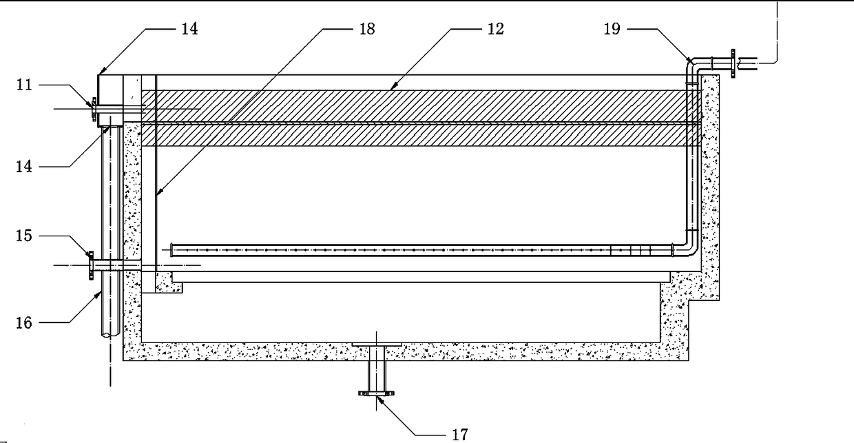
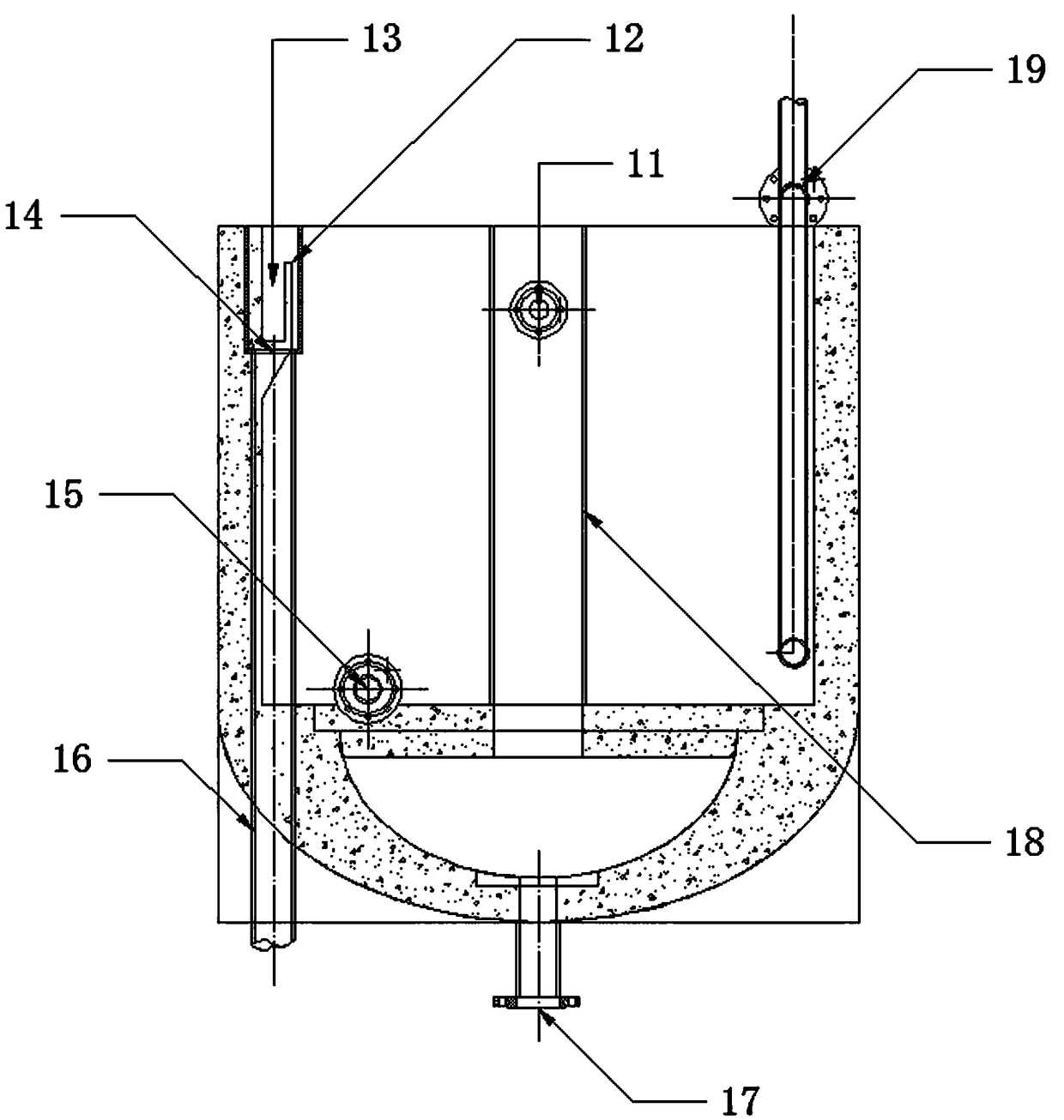
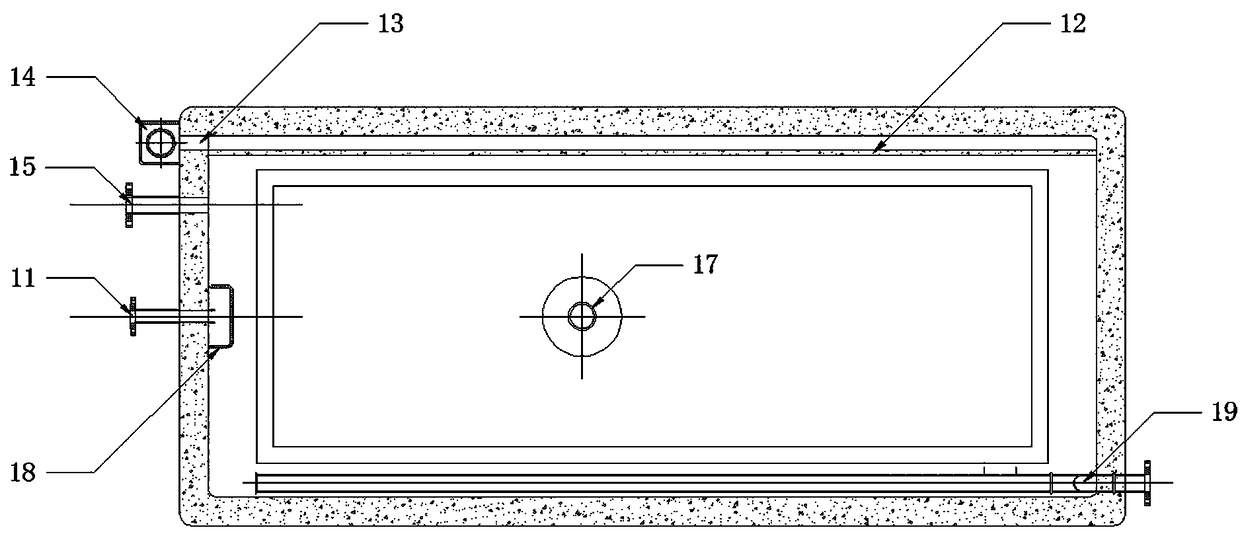
[0048] The electrolysis process of metal manganese of the present embodiment is mainly completed in the turbulent flow electrolyzer, and the structure of the turbulent flow electrolyzer is as figure 1 , figure 2 , image 3 As shown, it includes a tank body and a diaphragm frame that separates the inner space of the tank body into an anode chamber and a cathode chamber. A liquid inlet pipe 19 is also provided in the tank body. Wherein, the liquid outlet 11 is located 3 to 5 cm below the liquid surface of the electrolyte, and the liquid outlet 11 communicates with the anode chamber through the communication pipe 18 .

[0049] The bottom of the tank body is provided with a mud discharge port 17 communicating with the anode chamber, the side wall of the tank body is provided with a discharge port 15 located at the bottom of the cathode chamber, and liquid supply pipes corresponding to the position of the cathode plate are arranged on the liquid inlet pipe 19. hole.

[0050] A...

Embodiment 2

[0057] The production system of metal manganese in the present embodiment, as Figure 4 As shown, the production system of metal manganese composed of the above-mentioned turbulent-flow electrolyzers includes an electrolytic system 1, a circulation purification system 2, a cooling system 3, and a regulating system 4 connected in sequence. The electrolytic system 1 includes a plurality of turbulent-flow electrolyzers. The electrolytic cell group and the circulating liquid collection tank, the overflow port 14 and the discharge port 15 of each turbulent flow electrolytic cell are connected with the circulating liquid collection tank; the electrolysis system is connected with the circulation purification system through the circulating liquid collection tank, and the The liquid inlet pipe 19 is connected with the regulating system.

[0058] The specific process of using this production system to produce manganese metal is as follows:

[0059] 1. Driving for the first time:

[00...

Embodiment 3

[0080] In this embodiment, on the basis of the foregoing embodiments, a control system 5 is added for the production system of electrolytic manganese metal, such as Figure 4 As shown, the control system 5 is respectively connected with the electric control valve, temperature sensor, and pH value sensor in the electrolysis system 1 , the circulation purification system 2 , the cooling system 3 , and the adjustment system 4 . Thus, the production process parameter signals can be centrally fed back to the control system 5 through the temperature sensors and pH sensors of each system, and the control system controls various electric control valves to automatically adjust the electrolysis process parameters, which improves the efficiency of the manganese metal production process. Level of automation and mechanization. Other parts of this embodiment are the same as those of the foregoing embodiment, and will not be repeated here.


PUM


Abstract

The invention discloses a turbulent electrolytic cell and a turbulent electrolytic production system consisting of the turbulent electrolytic cell. The turbulent electrolytic cell comprises a cell body, and a diaphragm frame for dividing the internal space of the cell body into an anode chamber and a cathode chamber; a liquid outlet communicated with the anode chamber is formed in the side wall of the cell body; an overflow port is formed in the upper part of the side wall of the cell body; and a liquid inlet pipe is arranged in the cell body. The turbulent electrolytic production system consisting of the turbulent electrolytic cell comprises an electrolysis system, a circular purifying system, a cooling system and an adjusting system communicated in sequence; the electrolysis system includes an electrolytic cell set and a circulating liquid gathering tank; overflow ports and drain ports of the electrolytic cell set communicate with the circulating liquid gathering tank; and the electrolysis system is connected with the circular purifying system through the circulating liquid gathering tank, and is connected with the adjusting system through liquid inlets pipes of the electrolytic cell set. The turbulent electrolytic cell solves the electrode concentration polarization and bubble effect phenomenon, and can prominently improve the electrolysis current efficiency; and the turbulent electrolytic production system consisting of the turbulent electrolytic cell can realize large scale, low energy consumption, automation and mechanization of the production of electrolytic manganese metal, and is higher in promotion prospect.

Description

technical field [0001] The invention relates to a metal diaphragm electrolysis process technology in the technical field of hydrometallurgy, and specifically refers to a turbulent flow electrolysis cell and a turbulent flow electrolysis production system composed of the turbulence electrolysis cell. Background technique [0002] China is the world's largest producer and exporter of electrolytic manganese metal, with production capacity and output exceeding 98% of the world's total. By 2011, China's electrolytic manganese production capacity had reached 2.4 million tons. Now, electrolytic manganese metal is the backbone of many regions in my country industry. [0003] Over the years, there has been no breakthrough in the production process of electrolytic manganese metal, and it is still a traditional process (the technology of the US Bureau of Mines in the 1930s). Due to the limitation of technological level, low level of equipment and backward degree of automation, the stat...

Claims


Application Information

Patent Timeline
Patent Type & Authority Patents(China)
IPC IPC(8): C25C7/00C25C7/06C25C1/10
CPCC25C1/10C25C7/00C25C7/06
Inventor 周勇
Owner 中锰(湖北)科技发展有限公司
Why Eureka
Try Eureka