
Vehicle cleaning device

A cleaning device and automobile technology, applied in the direction of vehicle external cleaning devices, etc., can solve the problems of ineffective protection, lack of portability, high waste rate of water resources, etc., to improve cleaning speed and quality, easy to carry, and clean The effect of improving efficiency

Inactive Publication Date: 2019-08-09
王盈盈
View PDF9 Cites 8 Cited by
  • Summary
  • Abstract
  • Description
  • Claims
  • Application Information

AI Technical Summary

Problems solved by technology

[0002] The existing car cleaning equipment mostly adopts fixed drum cleaning or fixed high-pressure water cleaning. The fixed drum cleaning belongs to contact cleaning. The car is fixed on the fixed position of the conveyor belt, and the rotating drum device is installed on both sides of the car. , use the cleaning brush on the roller to contact the car for cleaning; fixed high-pressure water cleaning is to fix the high-pressure nozzle on the side of the car to perform non-contact cleaning on the side of the car; although these two cleaning methods can clean the car body relatively clean, However, they all have certain limitations: First, such equipment is installed in professional car washes, and occupies a large area, is expensive, and has no portability at all. Therefore, users often use rags and other tools to manually clean the car body. Scrubbing, for more stubborn stains, often use your own booster pump to wash the car, and the water pressure of the household booster pump is not easy to control, direct impact may cause damage to the car body, like car windows or special parts on the car body It cannot be effectively protected, and manual flushing has a large waste rate of water resources, and the cleanliness after cleaning is often not satisfactory

Method used


Image

  • Vehicle cleaning device
  • Vehicle cleaning device
  • Vehicle cleaning device

Examples


Embodiment Construction

[0023] The technical solutions in the embodiments of the present invention will be clearly and completely described below in conjunction with the accompanying drawings in the embodiments of the present invention. Obviously, the described embodiments are only some of the embodiments of the present invention, not all of them. Based on The embodiments of the present invention and all other embodiments obtained by persons of ordinary skill in the art without making creative efforts belong to the protection scope of the present invention.

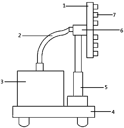
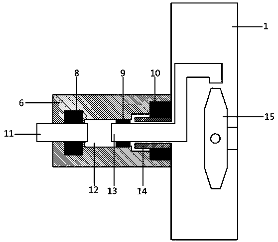
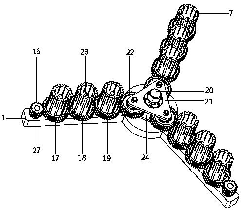
[0024] see Figure 1-9 , the present invention provides a technical solution: a car cleaning device, including a diverter box 1, a connecting water pipe 2, a water tank 3, a cart 4, an electric cylinder 5, a socket 6, an annular brush 7 and a controller, the water tank 3 and The electric cylinder 5 is fixedly placed on the trolley 4, and the connecting tube 6 is fixedly installed on the end of the push rod of the electric cylinder 5. The sealing...


PUM


Abstract

The invention discloses a vehicle cleaning device, which comprises a flow dividing box, a connecting water pipe, a water tank, a cart, an electric cylinder, a receiving barrel, an annular brush and acontroller. The annular brush in the device can make dense spiral curve movement in the cleaning process, and thus the cleaning efficiency of the device is improved; when a color recognition sensor recognizes that the annular brush at the position corresponding to the color recognition sensor is located in a 'special color' wash-free area, a solenoid valve on a spray head at the position is closed, a water flow with the soaring pressure is relieved in an automatic pressure relief device in the vehicle cleaning device and then re-flows back into the water tank to be stored, and a vehicle body is protected well while water resources are saved; and the device is small in size, easy to carry and suitable for most occasions, the use requirements can be met only through a civilian tap, an operator can complete whole cleaning work only by slowly pushing a handle, and the cleaning quality of a vehicle is guaranteed while manpower is saved.

Description

technical field [0001] The invention relates to the field of car cleaning, in particular to a car cleaning device. Background technique [0002] The existing car cleaning equipment mostly adopts fixed drum cleaning or fixed high-pressure water cleaning. The fixed drum cleaning belongs to contact cleaning. The car is fixed on the fixed position of the conveyor belt, and the rotating drum device is installed on both sides of the car. , use the cleaning brush on the roller to contact the car for cleaning; fixed high-pressure water cleaning is to fix the high-pressure nozzle on the side of the car to perform non-contact cleaning on the side of the car; although these two cleaning methods can clean the car body relatively clean, However, they all have certain limitations: First, such equipment is installed in professional car washes, and occupies a large area, is expensive, and has no portability at all. Therefore, users often use rags and other tools to manually clean the car bo...

Claims


Application Information

Patent Timeline
Patent Type & Authority Applications(China)
IPC IPC(8): B60S3/04B60S3/06
CPCB60S3/04B60S3/06
Inventor 王盈盈
Owner 王盈盈
Learn More